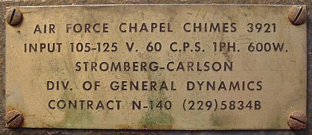
Air Force Chapel Chimes 3921
Made by Stromberg-Carlson division of General Dynamics
for the United States Air Force
Contract N-140 (229)5834B
Another rescue of doomed electronica brought to you by the Bunker of DOOM
Do you have the manuals for this? We would like to buy a copy. Please contact us by the address on the BunkerOfDOOM top page.
NOTE: for the 2006 New Years Eve, the chimes were run using one amplifier and a couple of PA horns. We rolled the beast out of the lab into the yard, and manually set 'er off! The results were spectacular and VERY loud! -so we really do want to find manuals for this item to restore it fully. It's too cool to let it go to waste. Thanks!
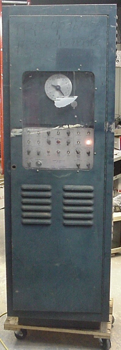
with flash
|
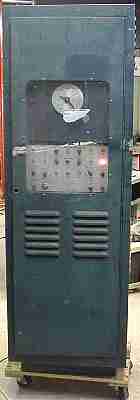
no flash
|
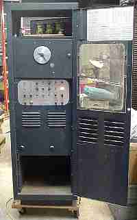
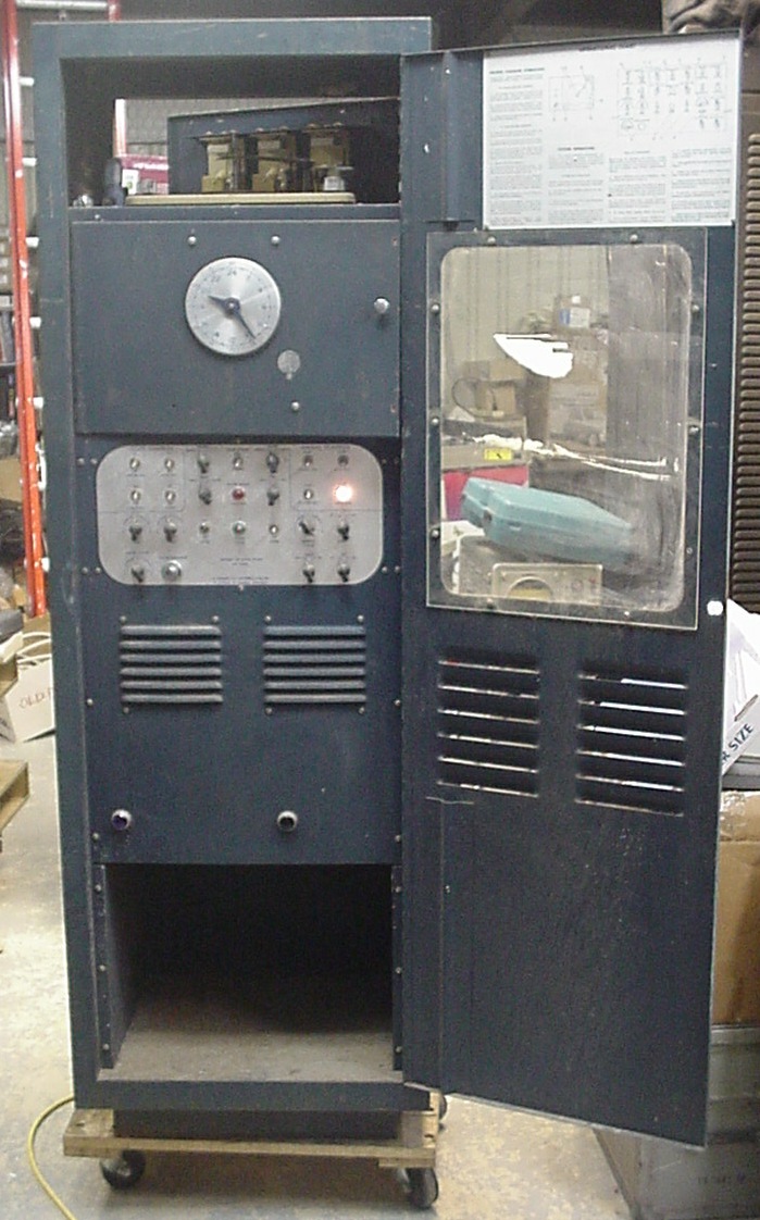
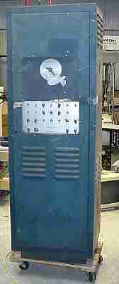
The door opens to reveal the 24-hour master clock, operators' console, and turntable. The louvers on the right have a monitor speaker and the ones on the left are a blower exhaust. The large violet jewels at the bottom of the panel are in front of the power amplifier pilot lamps.
|
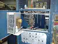
The master clock has four wheels and can invoke any of four programed functions at any time. The small set of wheels turn the days of the week dial indicator, and the day is advanced from Sunday through Saturday by tangs on the the master clock wheels pushing tangs on the week wheels and this is all detected by the switches shown at the bottom.
|
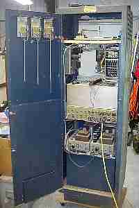
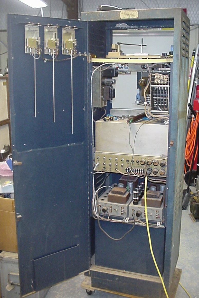
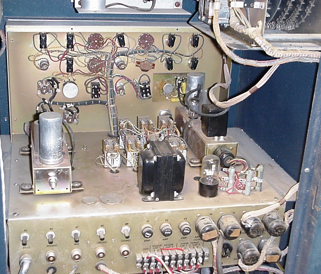
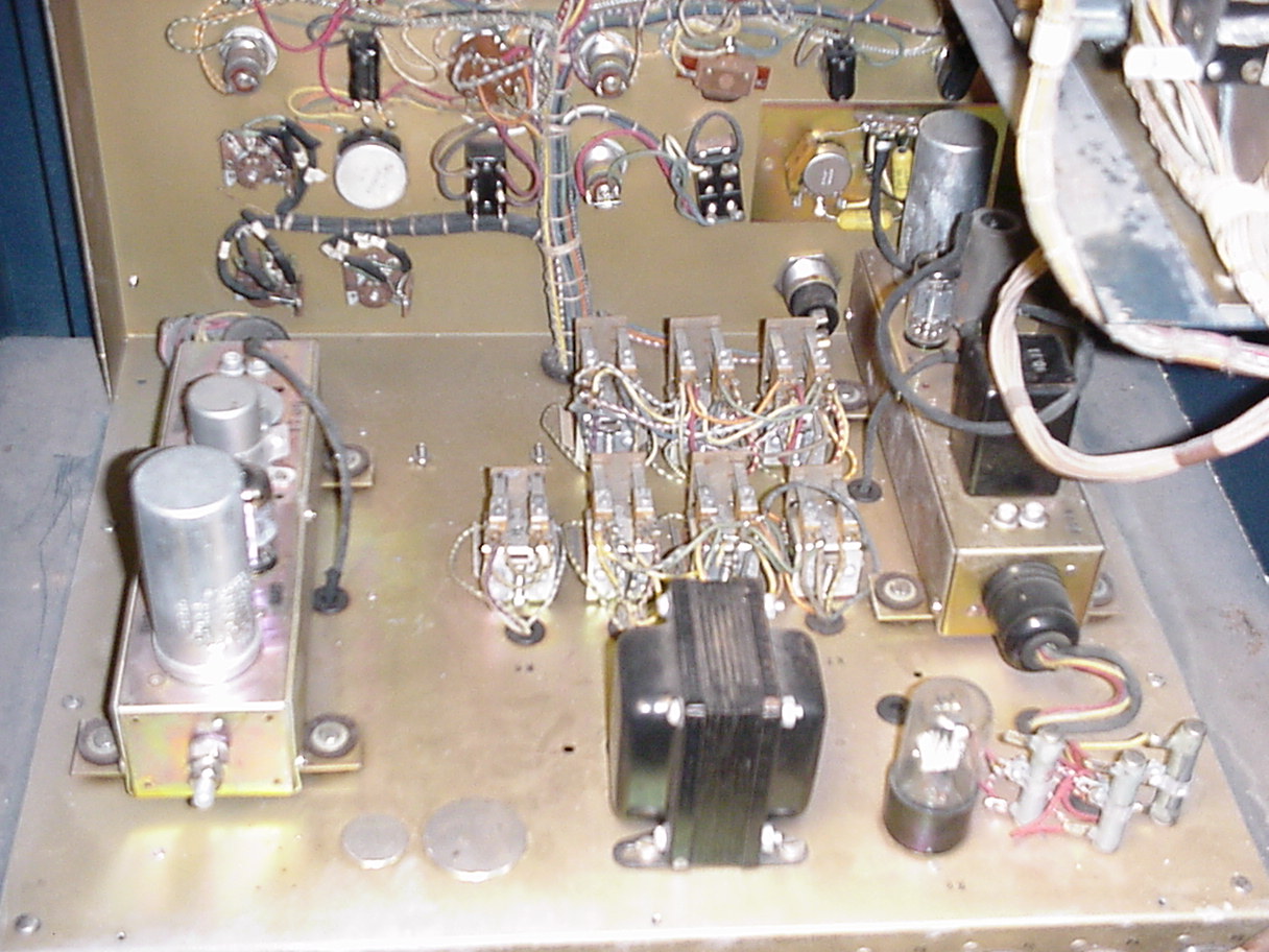
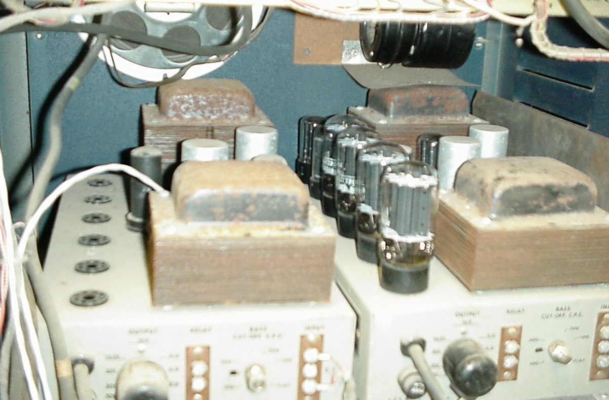
Rear view shows the chimes on the door (cover removed), turntable, next below on the left is the preamplifier and electronic brain power supply, and on the right is the chime control clockwork. Below this area is a chassis containing the electronic brain and preamplifiers. Below this is a pair of Stromberg-Carlson AP-55 amplifiers. Each is 50 watts. The amps sit on a box which is a storage space for recors or spares.
|

A short video of the chimes and chime control wheel in action. Sound courtesy of one of the original amplifiers.
|
Long ago, hand-operated or rope-operated bells have fallen into disuse by chrches in favor of mechanical or electronic automata. Shortly after the dawn of audio amplifiers and public address "horn" speakers, it became common practice to place electromagnetic pickup coils, not unlike modern day guitar pickups, near mechanical bells or chimes, and use clockwork to strike the chimes. A natural progression was to use electric motors to drive the clockwork, add a 24-hour clock mechanism, and invent a control system made of electromechanical relays and manual programming switches to further automate the process.
It is at this point in the timeline of churchbell technology that our piece finds itself. The operator sets the clock, programs certain times of day via metal tangs on a set of wheels (like a multiple-output incarnation of a professional Intermec timer), and programs the clergy's choice of bell sequences on another series of wheels. In basic operation, the clock signals the start and stop times of the bell control wheel. The bell control wheel has programming tangs on it which activate switches to energize solenoids to strike the chimes. The sound of the chimes is picked up by the pickups and sent through a preamplifier to a pair of 50 watt tube amplifiers, one for indoor and one for the bell tower. Additional switch and relay logic, the electronic brain of the unit, permits manual operation, selection of bell sequences, and reset functions after a power failure.
The images shown are fresh off the truck, after a little dusting and tweeking to find out if it is alive. It's Alive It's alive it's alive!! MOOOOOHAHAHAHAhahahahaaa!!
later on, we'll present it again after a more thorough cleanup and some amplifier repairs.