
A shot of both towers. The 5/8 wave square tower on the left is guyed. The 1/4 wave tower on the right is used to protect in that direction, and is self-supporting. Both towers date from the 1930's. |
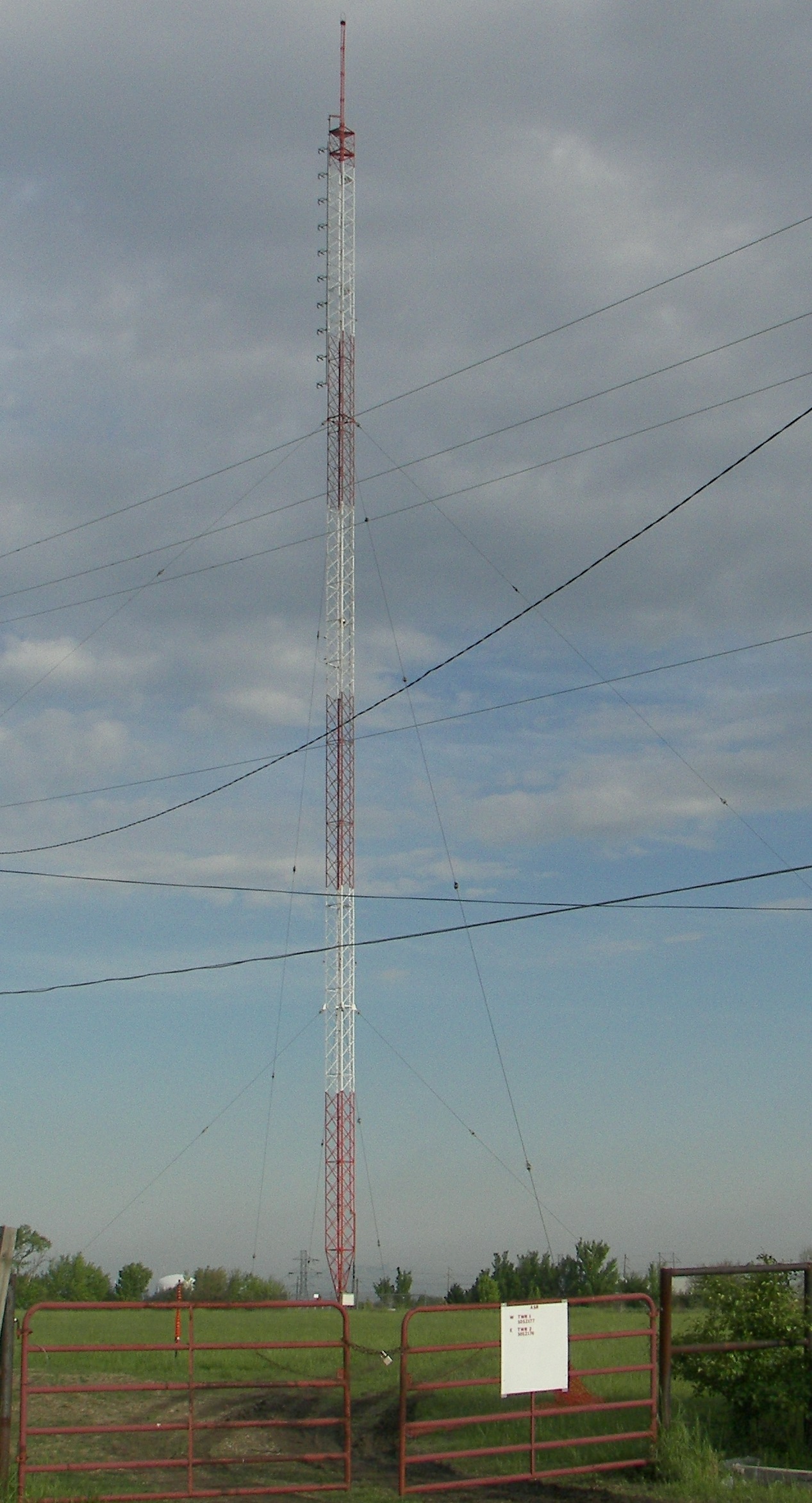
Just the 5/8 wave. The building (not shown, unfortunately) has an interesting history in that it was originally an old civil defense-rated (Conelrad) station and has a basement in which there was a diesel fuel tank and who know what else. The basement is filled in with sand these days. The generator remains, and is in another room. |
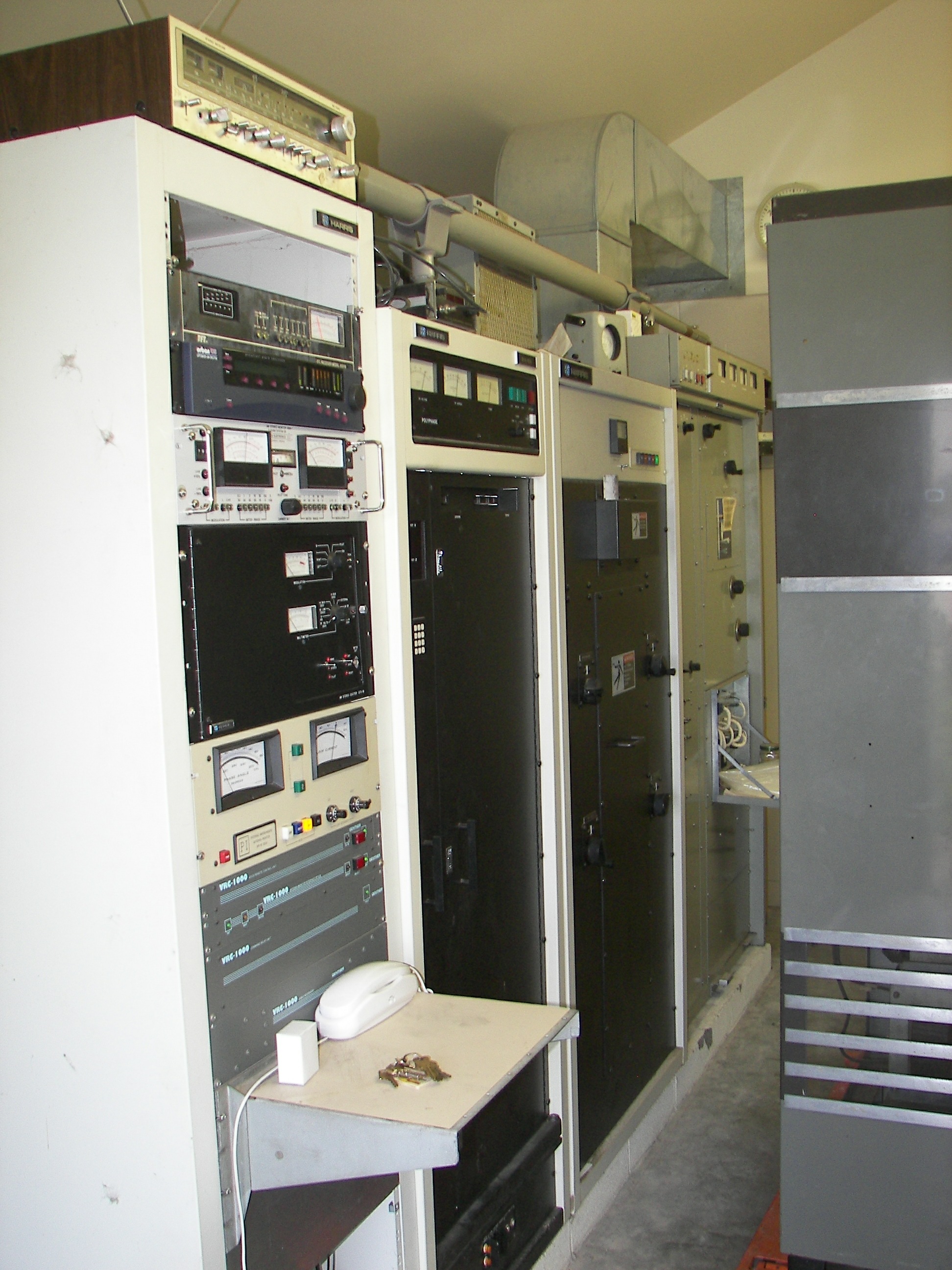
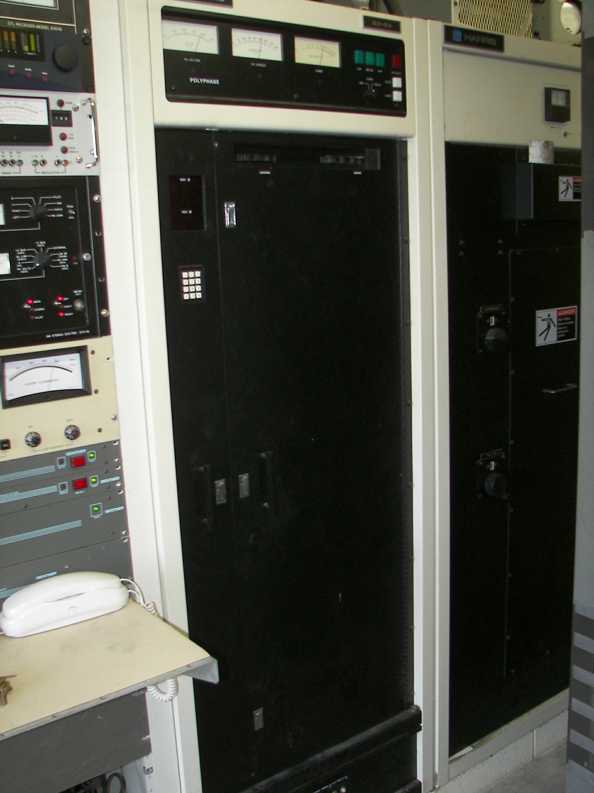
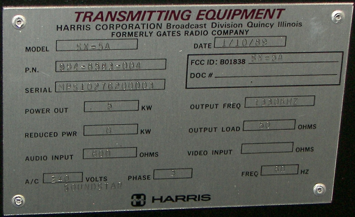
The racks as of 5/11/2008 are on the left. Front to back: audio rack, Harris 5KW AM, phasing cabinet, Harris 10KW FM backup. On the right is the cabinet of the RCA BTA-250L I was given. |
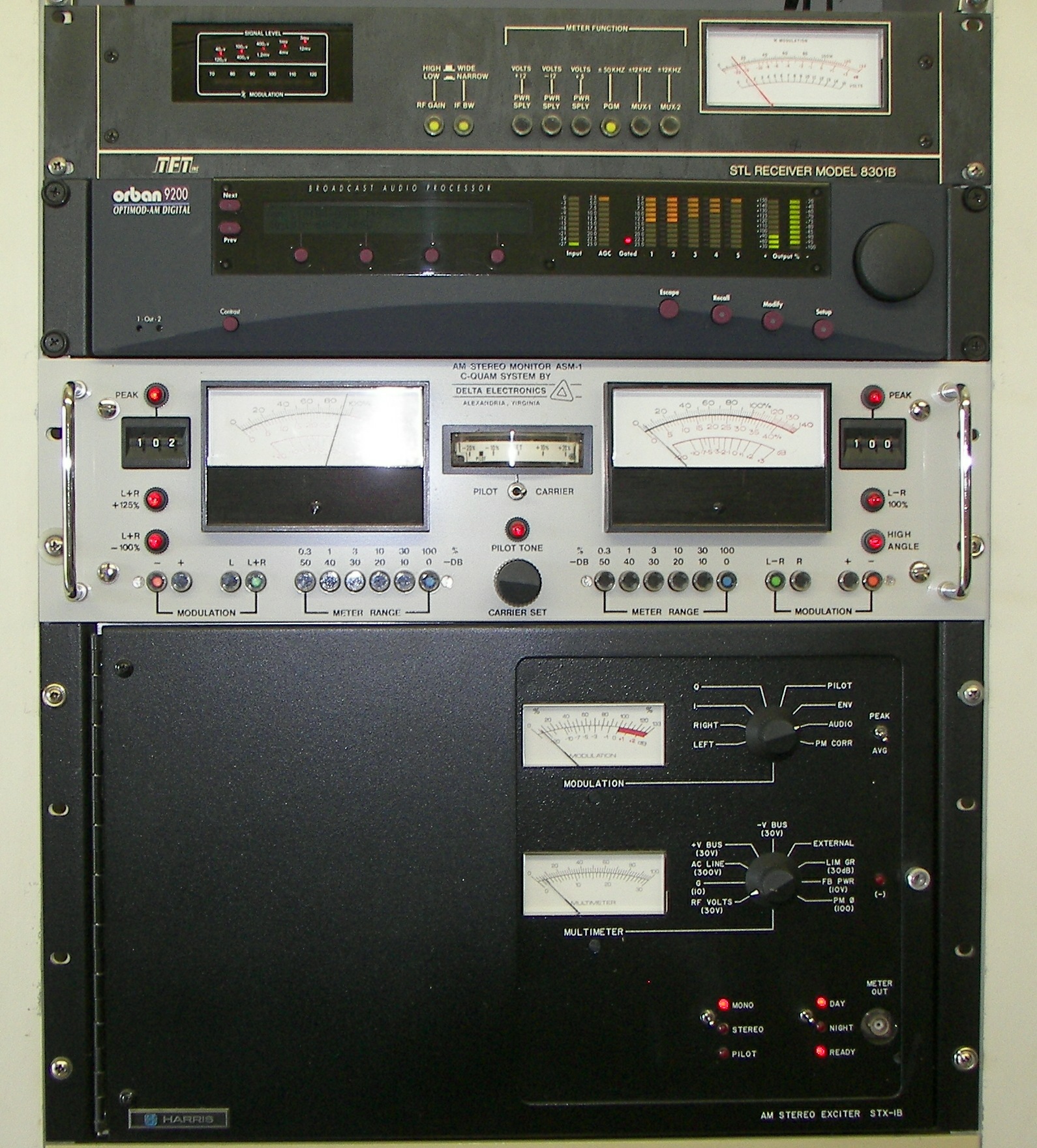
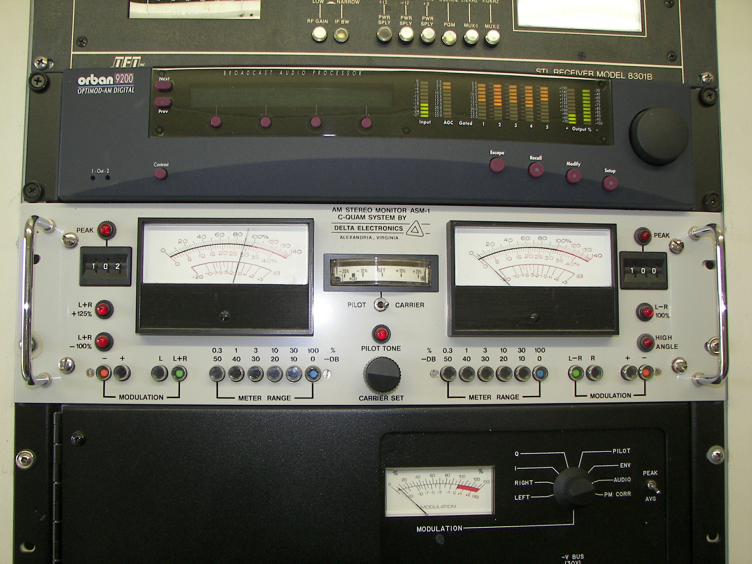
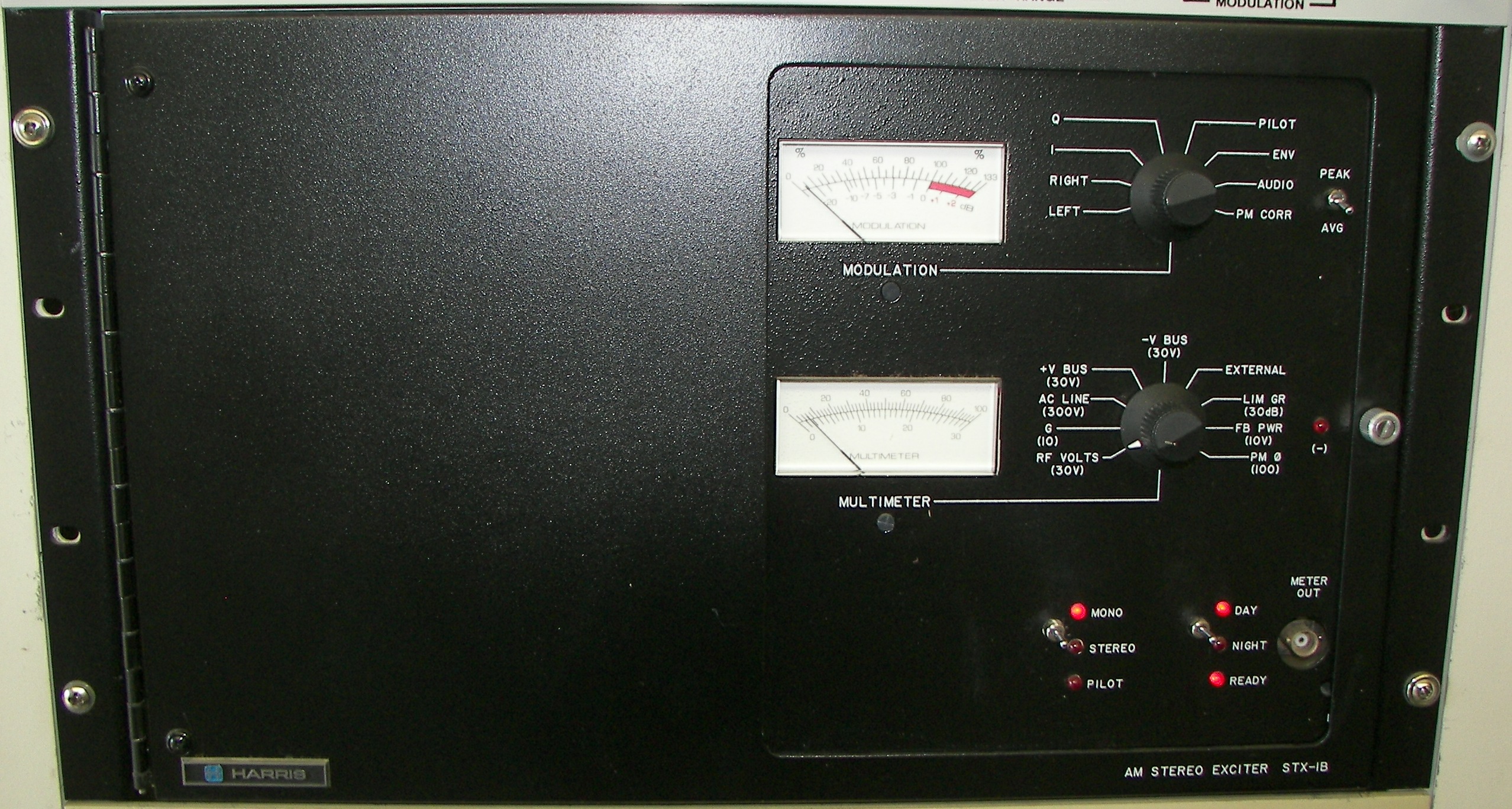
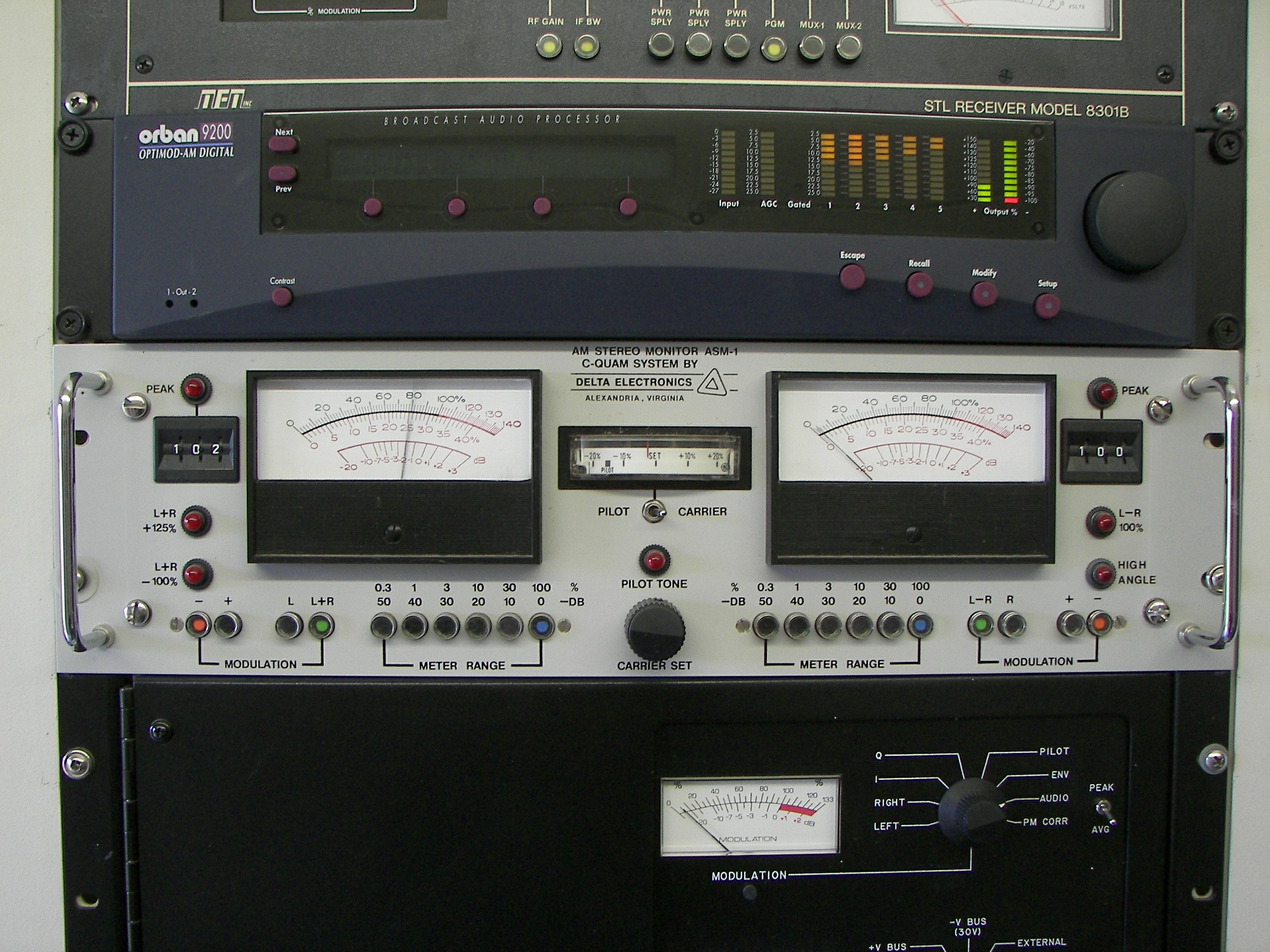
Audio gear. Top to bottom: STL (studio-transmitter link) unit, multiband audio processor (compressor/clipper), AM stereo monitor, AM stereo modulator. The C-Quam stereo system shown here is not used today. Pity, it is a much better system than the awful IBOC digital method. |
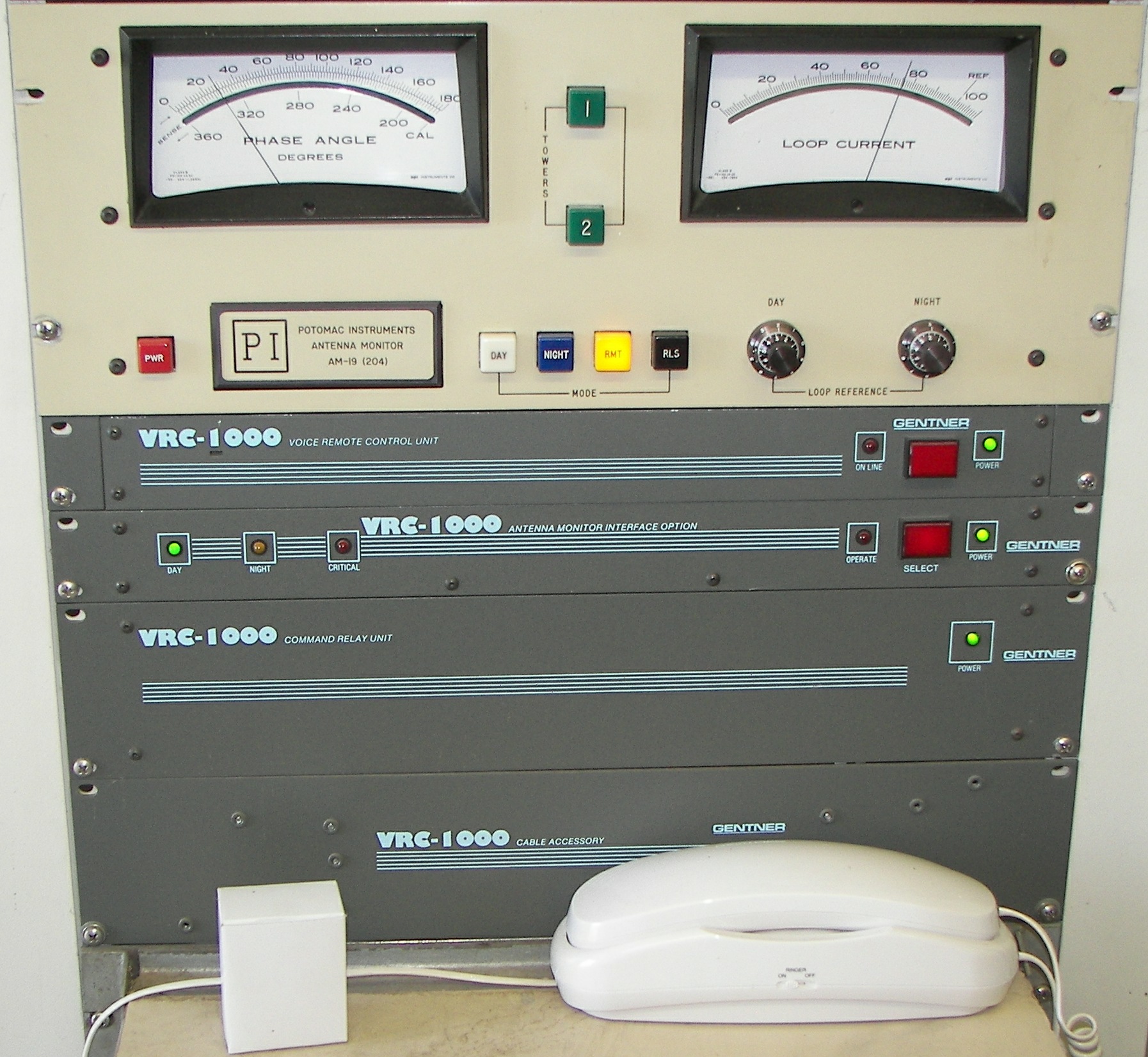
Antenna phase monitor and remote controls. |
|
|
|
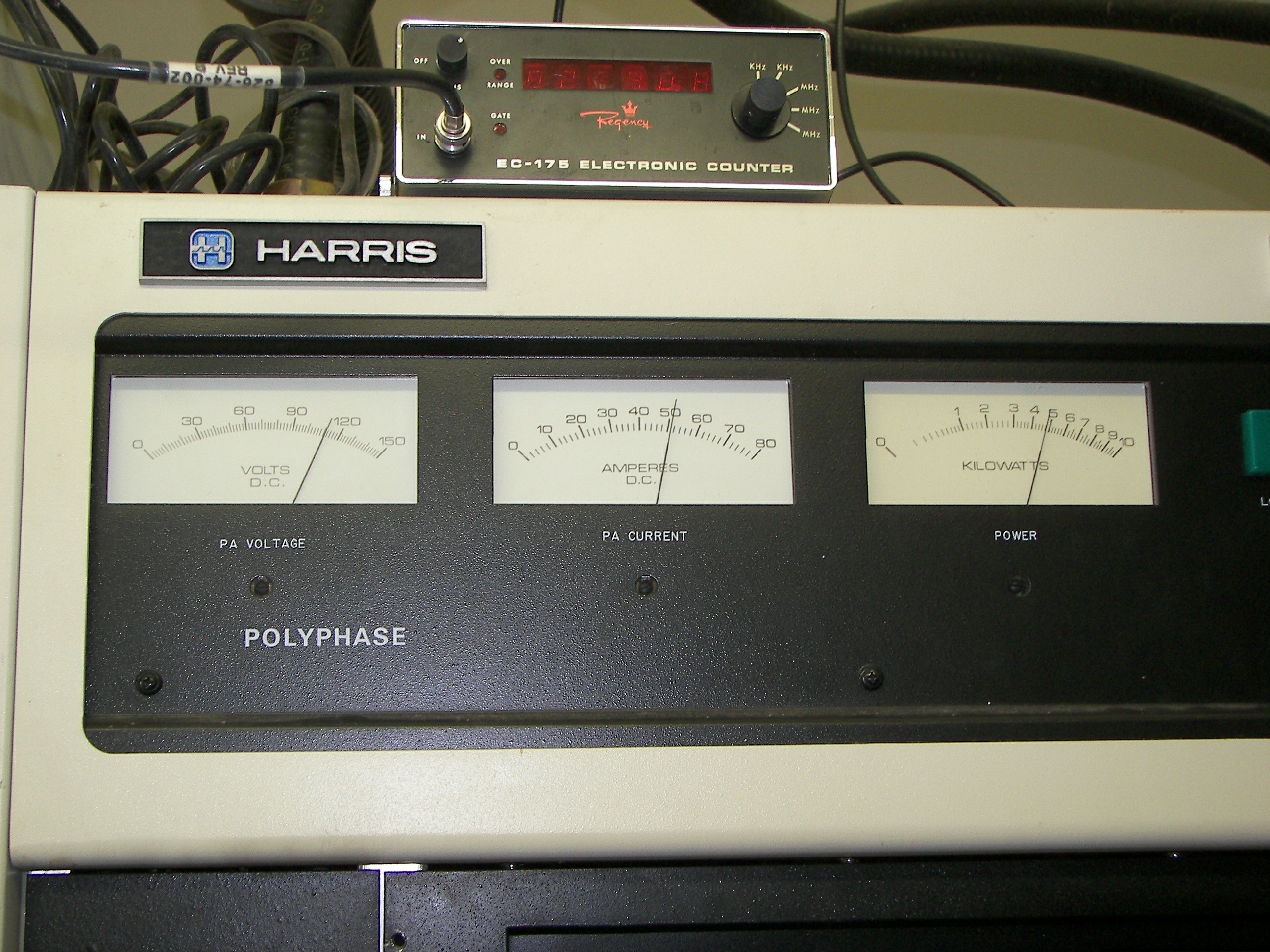
Meter readings on the Harris 5KW AM transmitter. It's a real nice solid state rig. Note the efficiency. Also, note the classic frequency counter! Just for casual inspection.. |
|
The 10KW FM transmitter is kept for standby use and its antenna is atop the 5/8 wave AM tower. The main transmitter is at another site. |
A control panel on the Harris FM unit. (disregard the mess, they are working in here) |

|
|
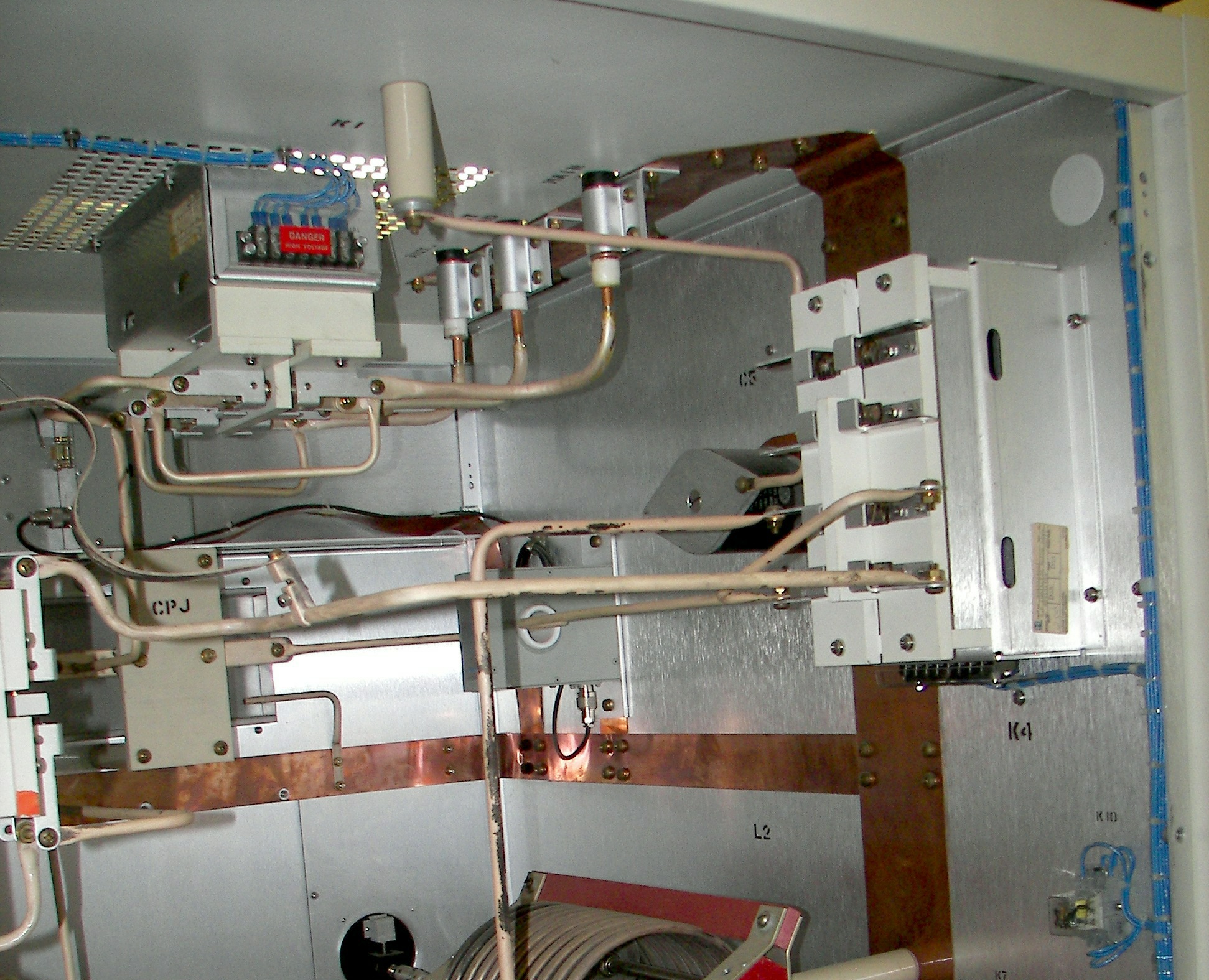
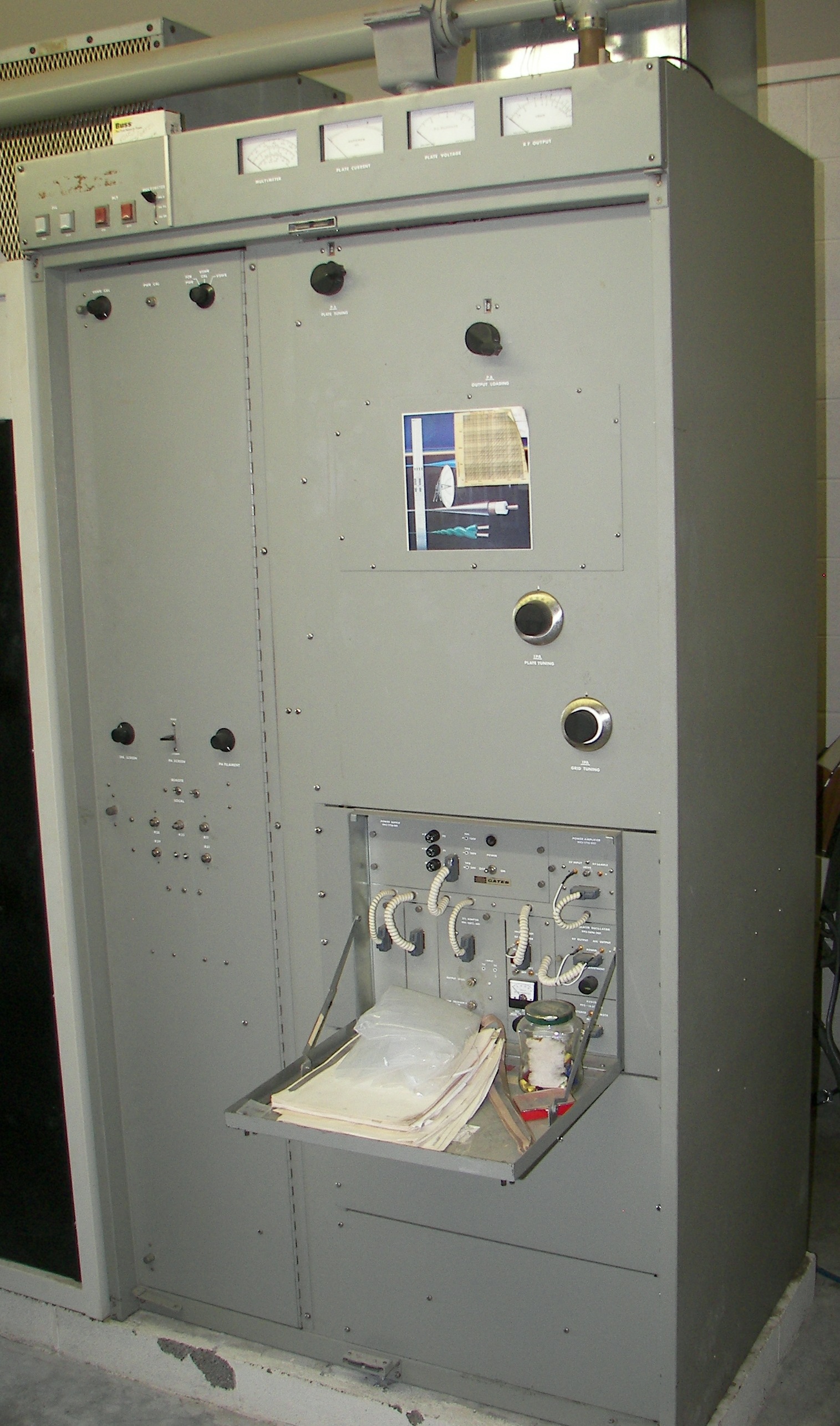
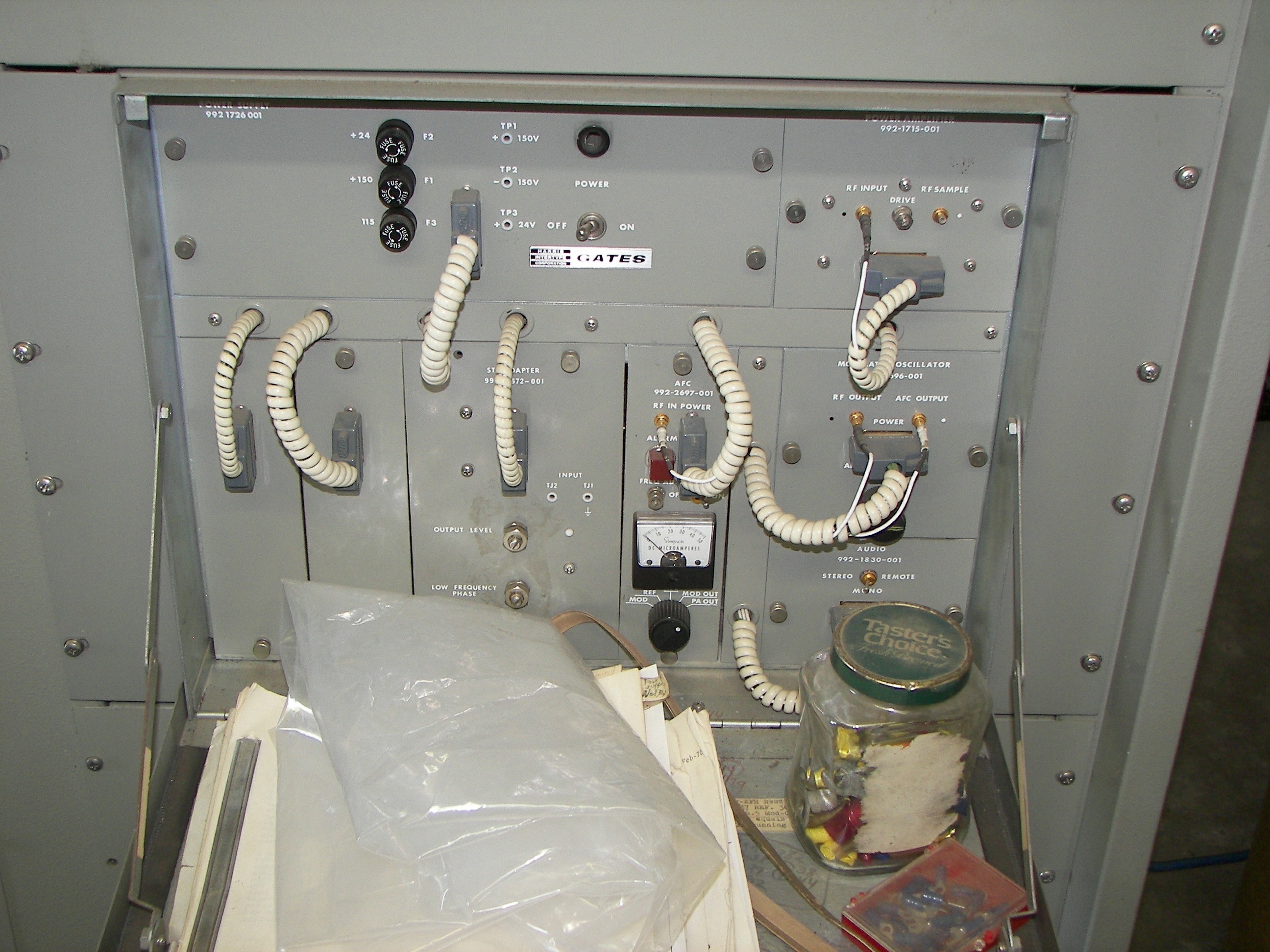
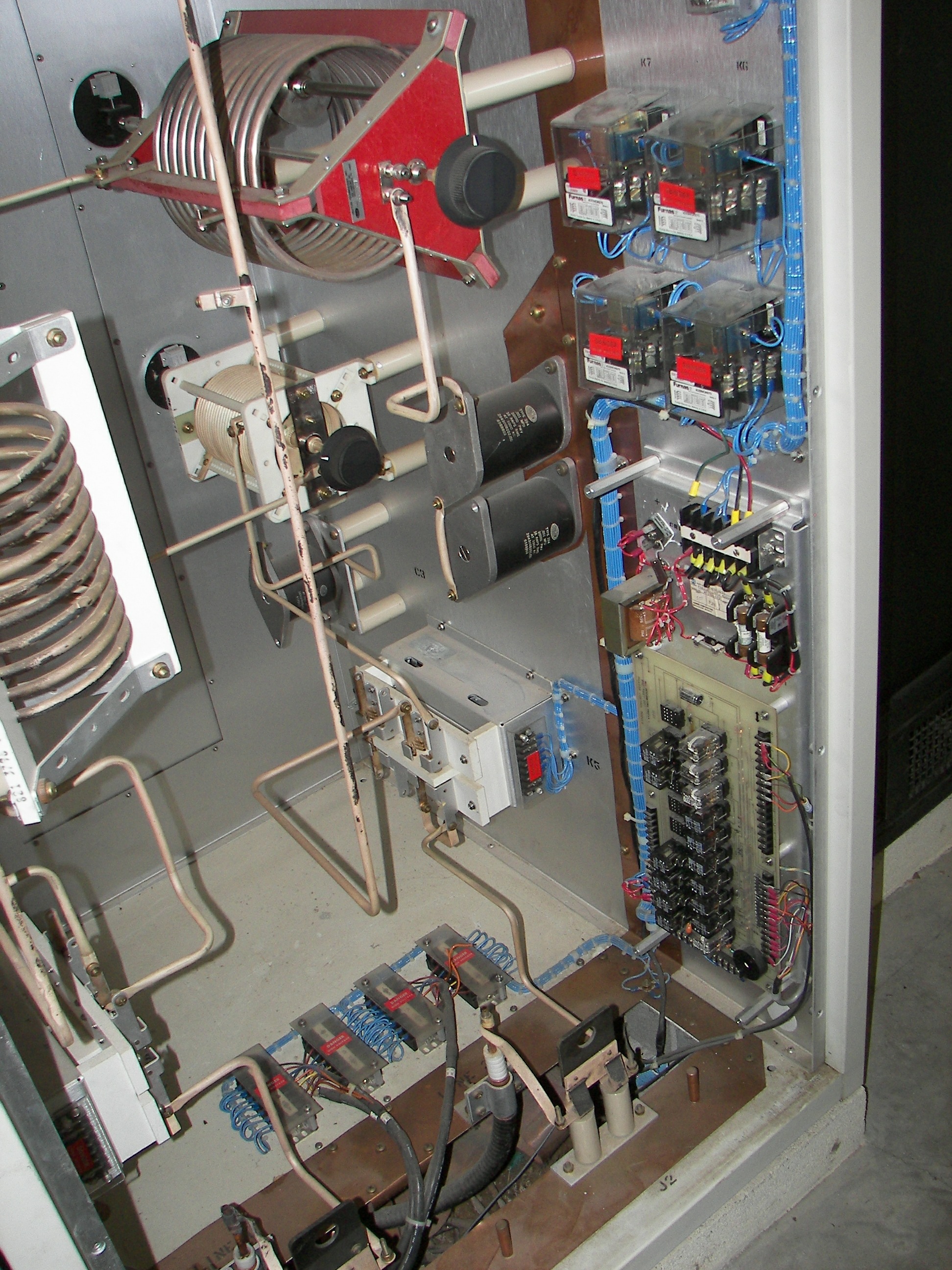
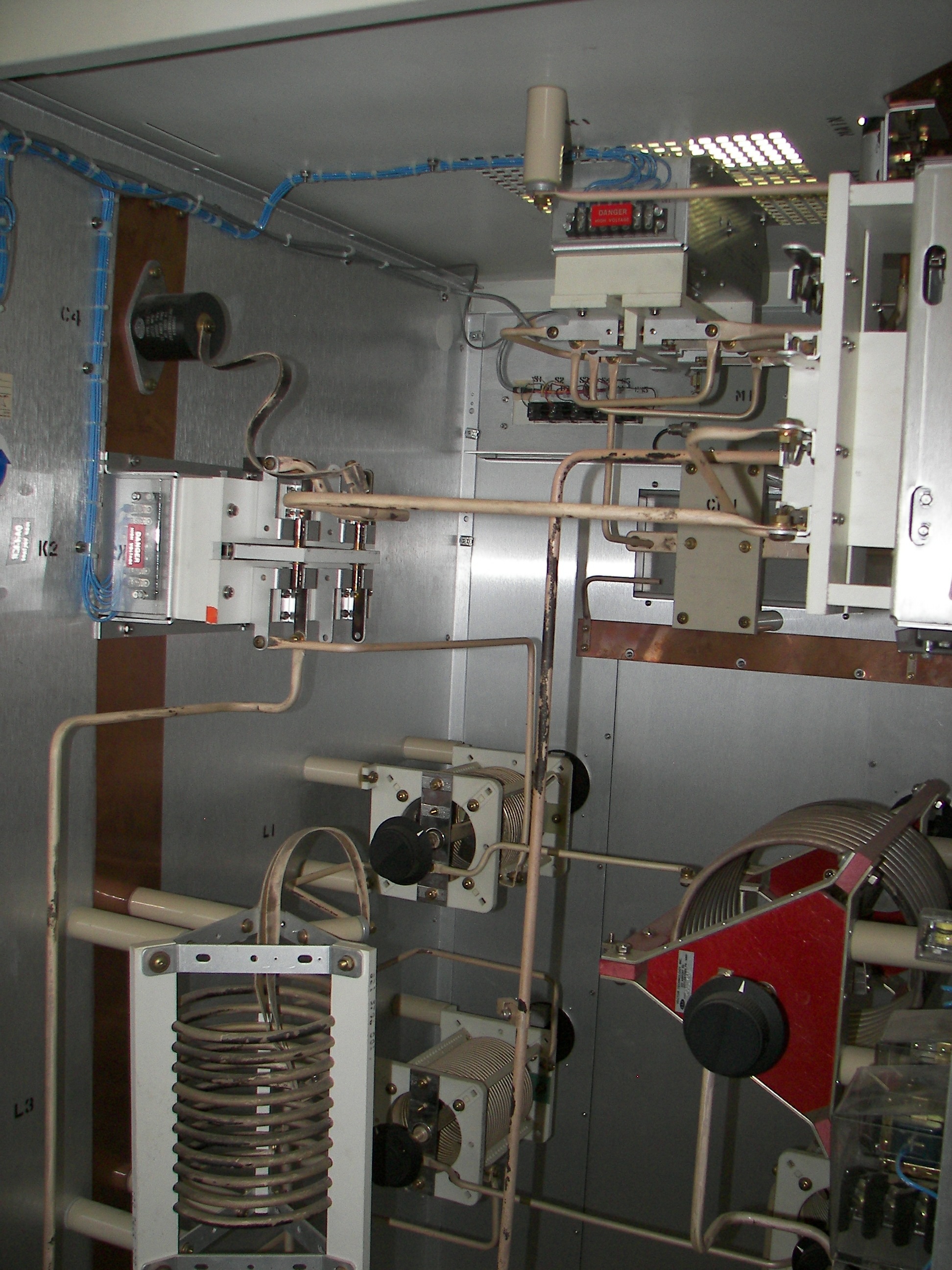
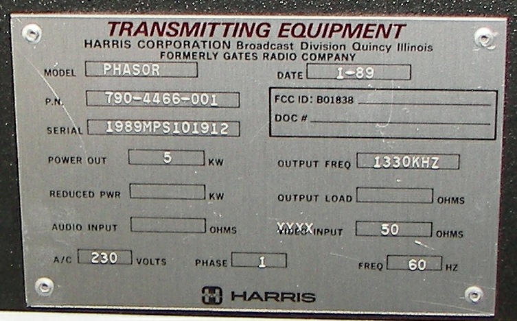
A few images of the inside of the AM phasing cabinet ("Phasor"), as the back was off for some work. Yes, there is 5000 watts of RF right there! |
|
|
|

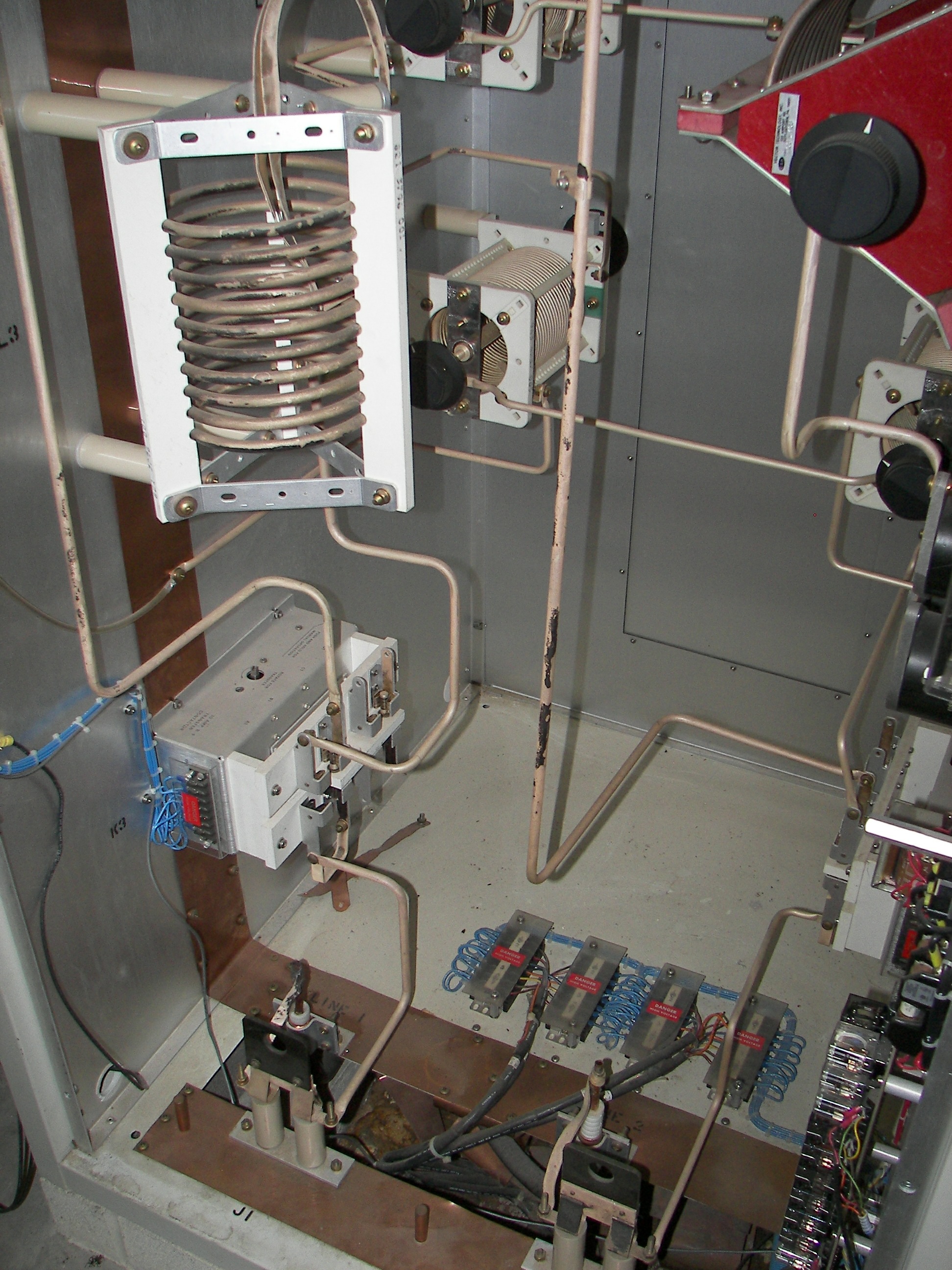
5/8" heliax lines in the bottom of the phasor |
|