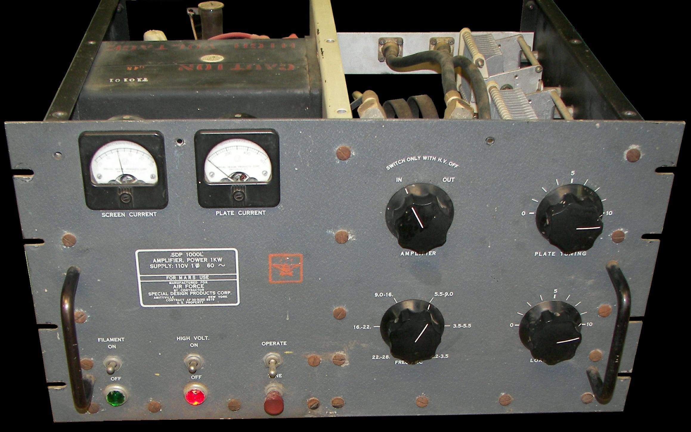
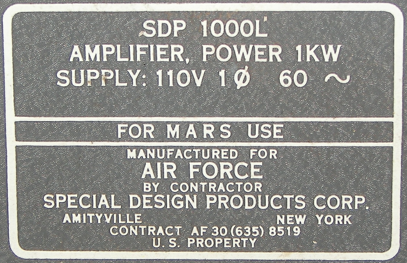
SDP 1000L RF Power Amplifier for MARS Use
Power Input 120VAC 60Hz / Dc Input 1KW / RF output 600 Watts
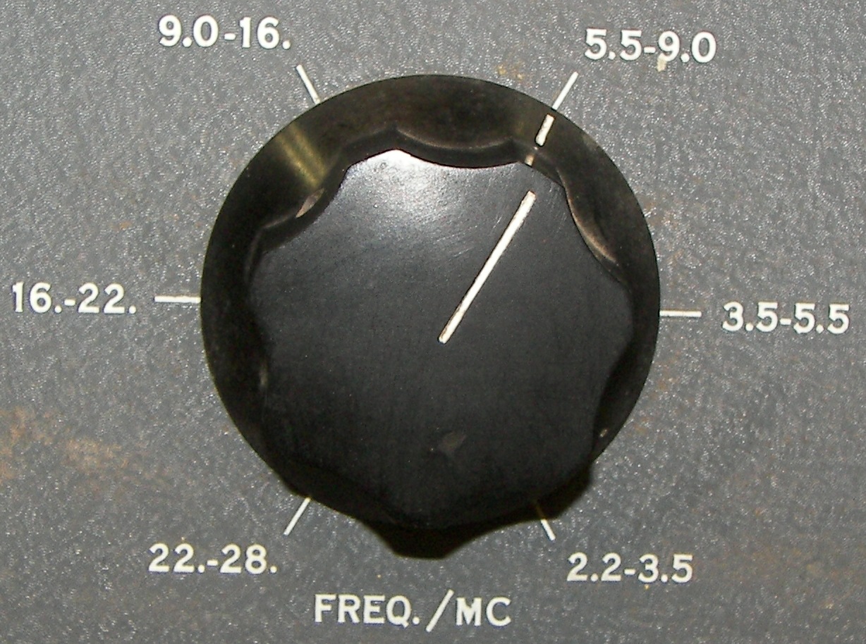
2.2MHz to 28MHz continuous coverage in 6 bands
Cathode-Driven Class AB Linear Amplifier MFG. about 1971-1975
|
|

|
|
|
|

|

|

|
|
|
|
|
|
|
|
|
|
|
|
|
|
|
|
This is a "grounded grid" amplifier.
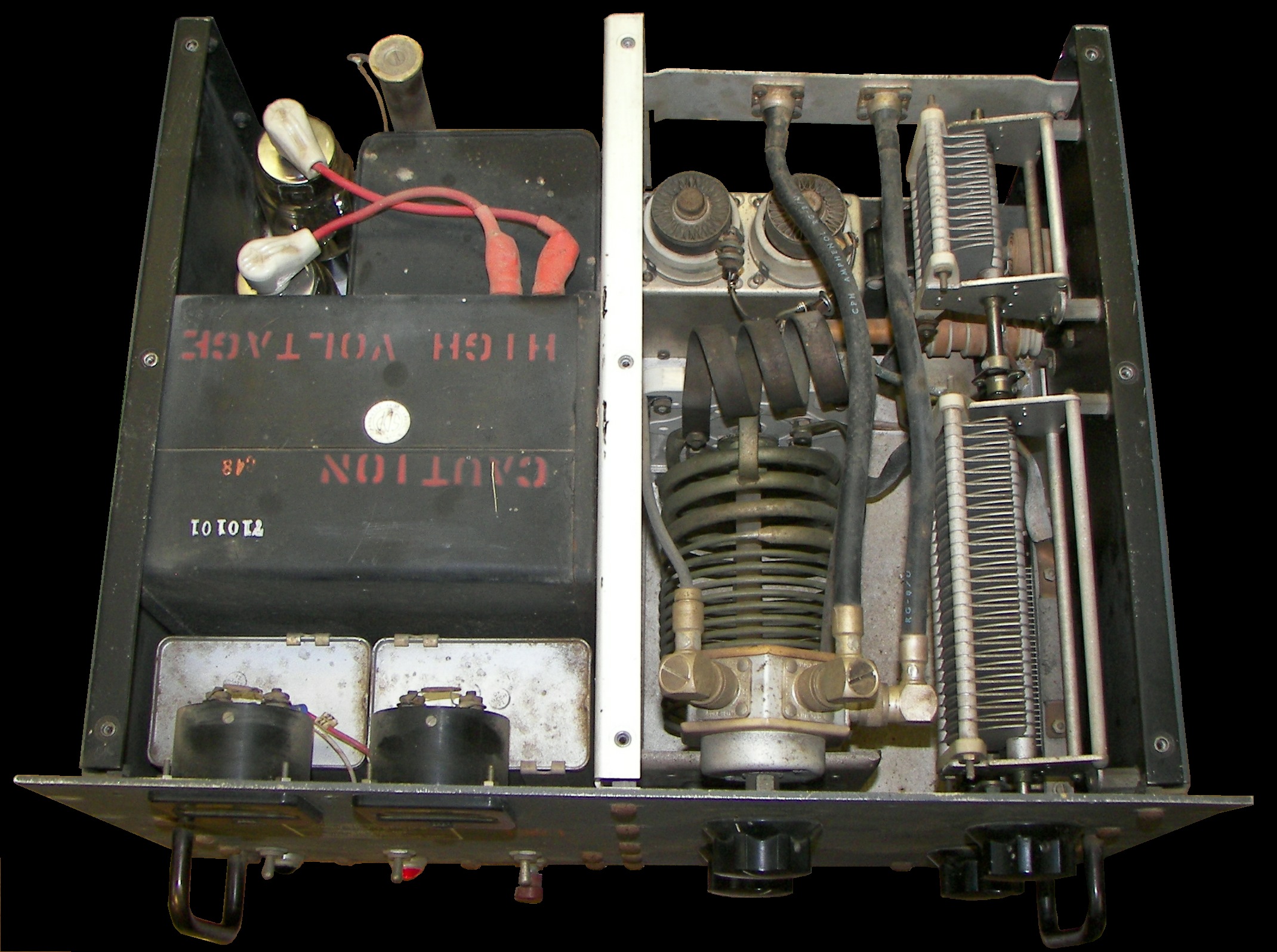
The screen and control grids are grounded for RF, but have the traditional DC voltages on them. The cathodes are driven by the transmitter without a tuning network and returned to ground through a large multi-winding RF choke and what measures as a 10 ohm resistor. In standby the plate voltage is 2100 volts, the screen voltage is 400V (seems high), and the control grid voltage is -155V. The HV is rectified by a pair of 3B28's but I have been told it had 866's before. Some voltages regulated by OA2 and OB2 VR tubes (that's what is installed, one never knows..)
The Pi-network is interesting in that it uses a common appearing B&W type coil and switch assembly wired in such a way as to place a second air variable, about 2 times the value of the main air variable, in the plate side to ground for the 2.2 to 3.5MHz range. The other positions from 3.5 MHz and up are wired in the usual manner, using varying degrees of the coil to cover 3.5 to 28MHz and using the single smaller plate tuning capacitor. Both plate tuning capacitors are on a common shaft system. I have not explored the absolute frequency ranges.
TR switching is done on the front panel using a knob that puts the amplifier "in" or "out" of the line.
The amplifier has non-Eimac (military?) 4X250 tubes and they are indeed ceramic, and of an older design that has less fins in the anode ring than the newer 4CX250B.
The blower was a little noisy, but quieted down after some operating time.
The two 4-position rear panel terminal strips are as follows:
top: [bias] [GND] [Eg2] [HV/2]
bot: [120V out1] [120V out 2] [key1] [key2]
NOTE: the to one seems to be for test points. Eg2 is of course the screen grid voltage. The HV/2 position is the center of a 200K bleeder resistor, so that one can use a 1KV DVM or Simpson meter to check the HV.
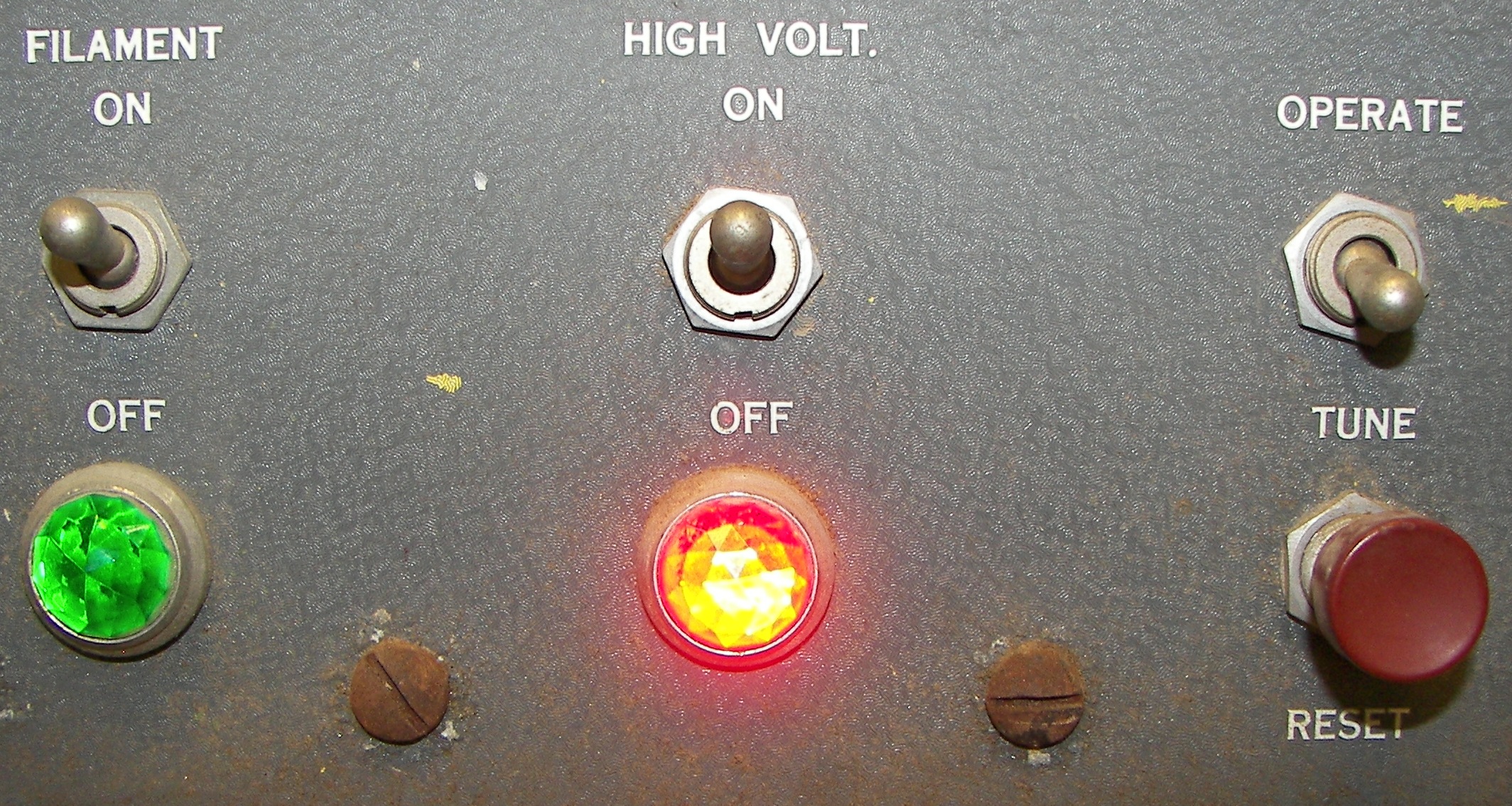
The lower strip 120V output can be used for a fan or whatever. It comes on when the filament switch is turned on. The keying circuit is 120VAC, not for people who don't know what electricity is.
The bias adjustment was set for about 100mA idling current.
The unit uses a 60K resistor of about 60 watts in series with three VR tubes to make the screen grid voltage. The unit was found with two 150V OA2's and one 105V OB2, and Eg2 was right at 405V. This seems high for the 2CX250B. I installed three 0B2WA's and have now 315VDC for the screen. Due to the high voltage drop and large sries resistance, the shunt regulator current, originally 25.5mA, did not increase much. It is now 28mA in standby with the HV on.
The overload circuit is in the cathode return line of the 4CX250B's. It is a simple latching relay coil of about 25 ohms resistance in parallel with a 50 ohm rheostat to allow for adjustment. The way it is set up, it will trip unless set near the insensitive end. To make 600 watts continuous RF, it had to be set right at the end of travel. For SSB without alot of speech processing it can be set about in the middle.
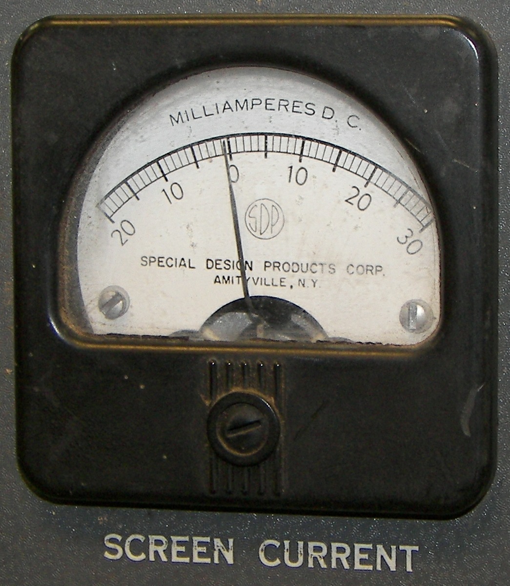
During tune-up testing, the operation switch was set to "TUNE" and the plate current dipped with the loading capacitor at "10". Then the drive was increased somewhat and the loading increased slightly including a tuning readjustment. In no case did the plate current seem to dip very much at all, but the screen current meter was an excellent indication of loading. The switch was set to "OPERATE" and the drive and loading were increased with only slight adjustments of the tuning required. Increase the drive until the acreen currrent in 10mA, then increase the loading to increase output, touch up the tuning, and repeat.
It was possible to get about 600 Watts out with 2000VDC, 500mA plate current and 10mA screen current. The efficiency dropped to about 50% at the higher frequencies. The SWR seen by the Japanese solid state tranceiver used as the driver was quite good over the entire spectrum. With 30 watts input, the amplifier provided 600 watts output.
It would not do to well for break-in operation because the T/R switch is manual and the keying is a little on the slow side, but otherwise there's no reason it would not be just fine for rather harsh or long-winded duty. It would even be fine for AM, if one would be satisfied with a nice 100 watt carrier and can avoid positive peak overmodulation which could trip the overload.
Since the unit operates on 120VAC and draws nearly 15 amps when running 1KW DC input, it is best to have a well-wired outlet so there is less line voltage drop. It is a bit sensitive to that with respect to the plate and keying relays, which will buzz on peaks if the line is weak. If the line voltage dips enough due to high plate current peaks (for instance if operated on an extension cord or an old outlet for the 1940's), the HV will be poorly regulated and the VR tubes can go in and out of conduction, leading to an unpleasant but seemingly harmless oscillatory behavior in the power supply.
The unit would not operate on the 160M ham band even at 1.99 MHz. The tuning capacitor was fully meshed. I guess they meant business when they said 2.2MHz. One could add a few pF to get there. The Pi-network is set up to switch in an additional section of air variable in the plate circuit on the low band, so if the added capacitance were connected to that additional variable capacitor only, it would not affect the other bands.
I'd like to find a schematic or manual and to learn more about its design. I like to keep these old things as they should be, and use them that way. This one seems to be in fine shape and certainly works well despite the tarnish and character of the years. If you have a schematic or manual, please contact the administrator listed in that link.