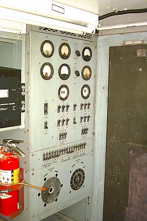
The image shows an oblique view of the electrical rack.
The images were taken after the work described in the article was completed.
The purpose of the power control rack in a military communications shelter is for proper monitoring and control of the input voltage and current to the shelter, as well as safely supplying power to AC-operated accessories such as lighting, outlets, and DC power supplies.
The shelter came with a 6 ft. high rack installed. The rack was filled with wiring, circuit breakers, voltage, amperage, reed-type frequency meters, and two large 3-phase variable autotransformers (variacs'). The aft side of the rack abutts a bulkhead in which three Crouse-Hinds 100 amp three phase power connectors are mounted. The connectors pass through the shelter wall and provide a convenient place to plug into shore power. The correct shore power connector costs $275. The rack also contained a 28VDC 100 amp power supply with breakers, DC voltage and current meters, as well as 115VAC 3 phase metering for 60 Hz and 400 Hz.
The image shows an oblique view of the electrical rack.
Since our requirements are mainly 115VAC 60 Hz and the 60Hz variac was burned, the decision was made to remove both the 60Hz and 400 Hz variacs, and bypass them for now. This removes the ability to adjust the voltage precisely, but that issue will be later addressed by means of a new 60 hz variac or a constant voltage (ferro-resonant) transformer for those loads which are voltage-sensitive. The 400 Hz variac will not be reinstalled.

The image shows the removed 3 phase variacs. The 400 Hz one is on the left.
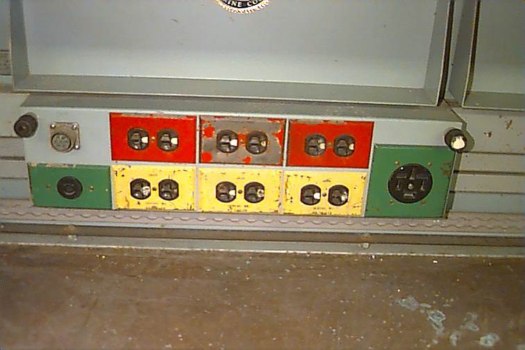
The image shows one of three main groups of power outlets. The red outlets are on the 400 Hz lines, and the yellow outlets are on the 60 Hz lines. The covers will be painted at a later time. Additionally, there are 12 more 115VAC outlets above and below the workbenches on each side.
Since the original air conditioning system, as well as half of the 115VAC outlets in the shelter were operated from 400 Hz power, the main 400 Hz 3 phase power input wires (#6 guage) were removed from the 400 Hz input connector on the aft bulkhead, and inserted into the 60 hz input connector along with the original (#6) 60 Hz input wires. The input connector is rated to accept anything up to a #2, so this was not an issue. Now, the 400 Hz circuit breakers, metering, and outlets feed from the same 60 Hz input as the original 60 Hz power. This is not exactly 'kosher', as the breakers are rated for 400 Hz, but a test showed that they do in fact work well with 60 Hz.

The image shows the front view of the panel. The image is a composite, therefore the change in tone of the panel color about halfway down.
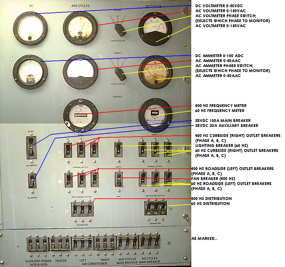
The image shows the panel with labels pointing out the controls
The shelter includes two 8" high speed exhaust fans. Such motors will not operate from 60 Hz power. A small 400 Hz static converter will be installed for operation of the fans, and the fan power wiring , which has its own circuit breaker, will be rewired to the converter.
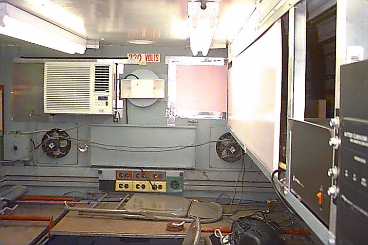
The image shows the view of the front interior of the shelter. The 400 Hz fans are visible, as are the off-high-low fan speed control boxes. In the center, to the right of the air conditioner, is a rectangular two-lamp emergency light.
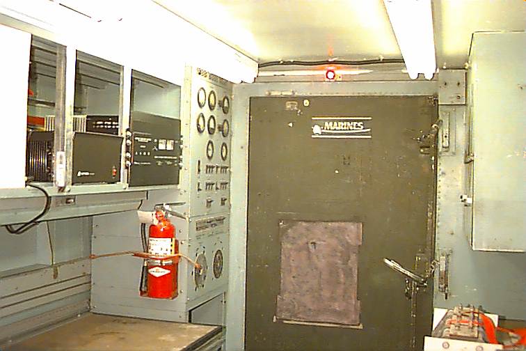
The image shows the view of the rear interior of the shelter. The door and electrical panel are visible, as are some paperwork drawers on the right.
The new 60 hz single phase air conditioner is now supplied by one pole of the 25 amp circuit breaker and #10 wiring originally set up for the 400 Hz 3 phase military air conditioner. This is an improvement because the air conditioner sometimes tripped the 15 amp breaker supplying the standard outlets into which the unit had been temporarily plugged. The outlet distribution breakers in the rack are fast-trip magnetic units, and did not handle the sir conditioner's power-on electrical surge well in warm weather, resulting in nuisance trips. The air conditioner is wired directly into the junction box which previously supplied the military unit.
The rack panel includes a 60 Hz and 400 hz frequency meter, ammeter, and AC voltmeter. It was found that the 400 hz voltmeter and ammeter are fairly accurate at 60 Hz, so they were left connected. The 400 hz frequency meter was disconnected.
An emergency light was installed for safety. If the power fails, the light comes on in the otherwise pitch-dark shelter. The light was modified so that its battery may be disconnected by means of a switch to prevent discharge when the shelter is unused and unpowered.
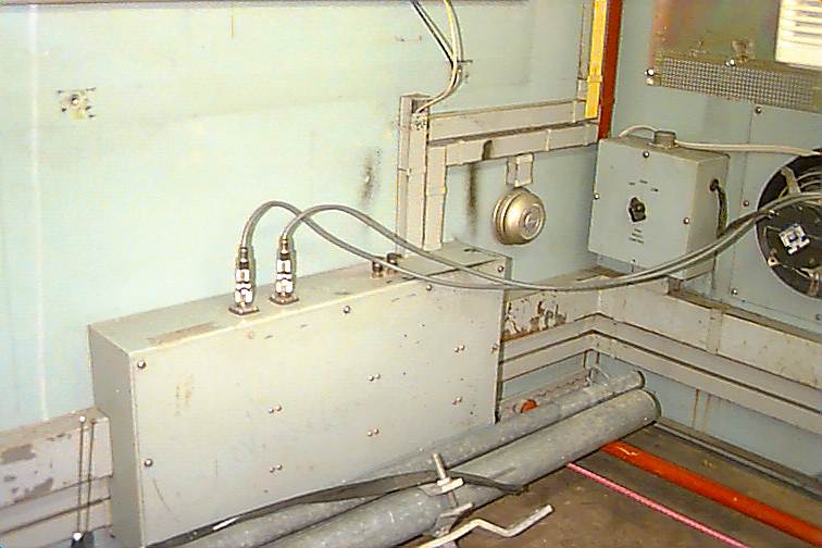
The image shows the through-wall bulkhead box. Two coaxial connectors and a pair of telephone binding posts come out the top. Inside, power wiring goes to outside connectors on the driver's side of the enclosure. The walls are in need of paint. This will be done at a later time. The nomenclature will be carefully masked, and the paint will be applied.
DC power is a must for operating a wide range of communications equipment. 12VDC and 24VDC are provided by two regulated power supplies. The existing shelving was made use of by adding brackets made of 1.5"x1.5"x0.125" aluminum angle stock to form "rackmounts" for the heavy power supplies. Their weight rests on the robust shelf. They are held in place front-to-back by the rack aluminum "rack rails", and they are tied down to the shelf by strapping of the type used to hang air conditioning ductwork in buildings. One side of the strap was bolted firmly to the floor of the shelf, and the strap was passed over the power supply, where the free end is tightened towards the shelf floor by a long screw which passes through the shelf floor.
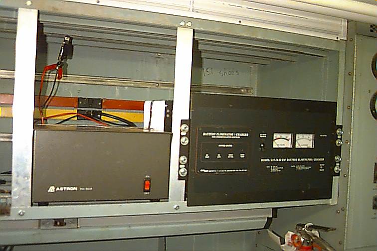
The image shows two DC power supplies. The one on the right is an Astron 12VDC 50 amp unit, and the one on the left is a Newmar 24VDC 60 amp unit. The Newmar is also designed to charge a 24VDC battery and will be interconnected to the vehicle's electrical system. Note the 115VAC outlets on the rear wall of the shelf.