Installing Aux. 24V and 12V Power and an AN/VIC-4 Intercom in an M35 Truck
Inside the shelter. Excuse the mess, it's a work in progress. It is also operational and ready to roll.

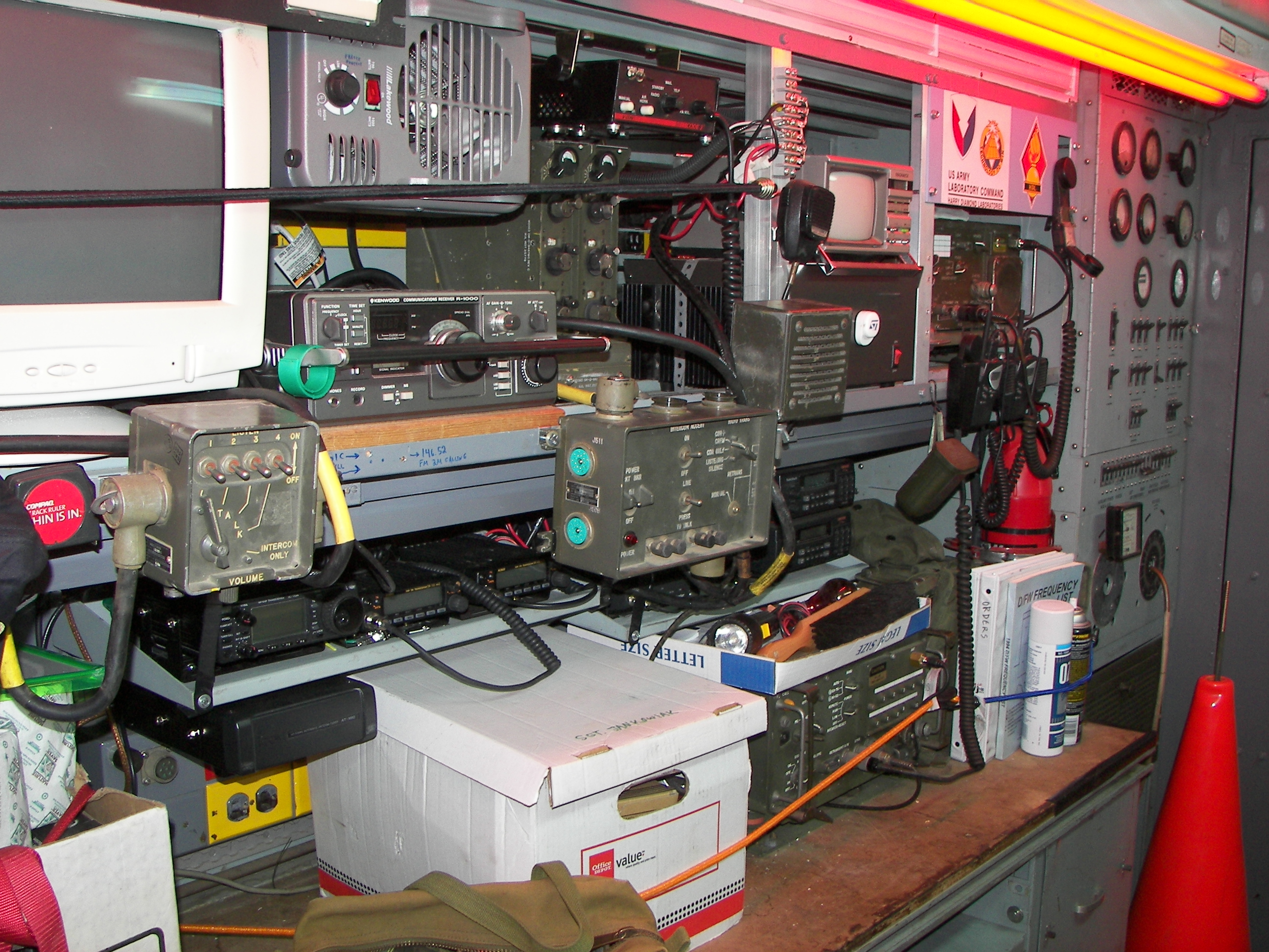
Looking forward from the back of the shelter. On the right is the communications and power equipment. On the left is storage for antennas, masts, and personal equipment. The yellow-looking lights are actually a narrow band red, and the white ones are blue-green. The effect is that all the lights are on for white light, and the red ones alone for night operations. |
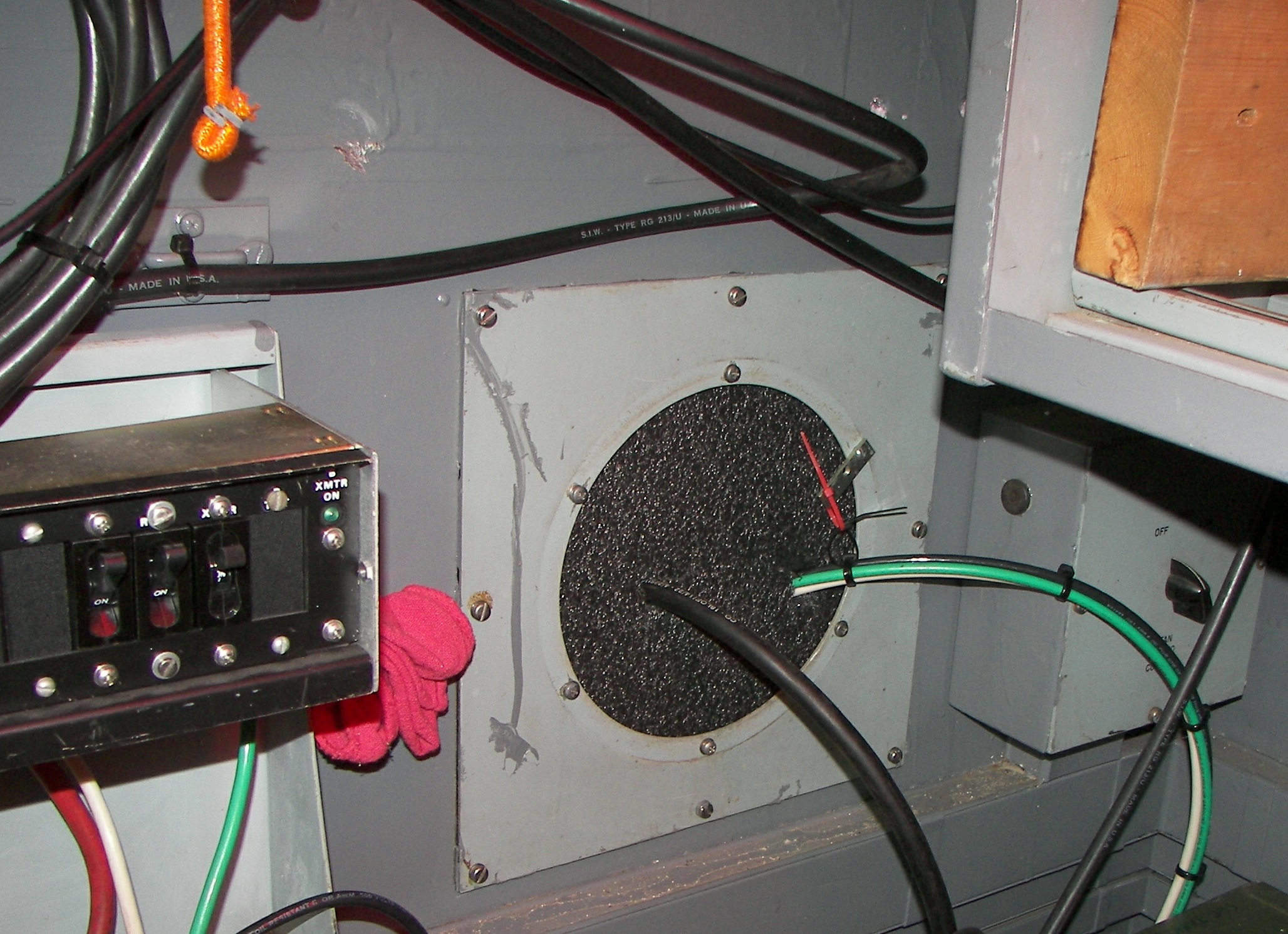
View of the inside of the large foam gland made for temporarily passing the 6-guage power wiring and the intercom cable through. The other side of this is shown here. |

close-up of dense foam block and note the power cable, being heavy, is temporarily held by a couple of small wire ties. There was a high volume 400Hz 5000RPM exhaust fan there, but it was removed. No 400Hz power anyway. |
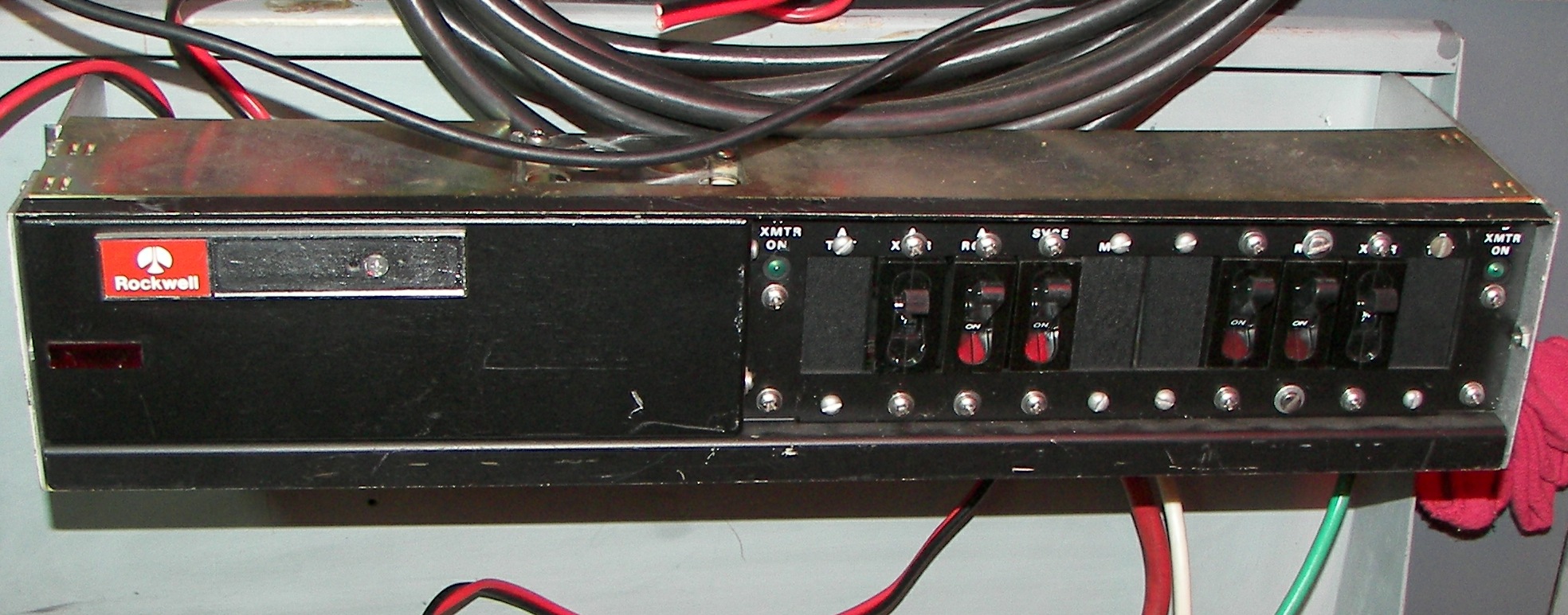
Rockwell breaker panel, The unit was modified and two 100A DC breakers added. One is for the 24VDC line and one is for then 12VDC line. The 6-GA wire is rated for only about 90 amps and the single ground has to carry all the return current. The contactor as mentioned will carry 40 amps continuously, so the breakers are there for vehicle-shelter disconnect, emergencies, and accidental short circuits. |

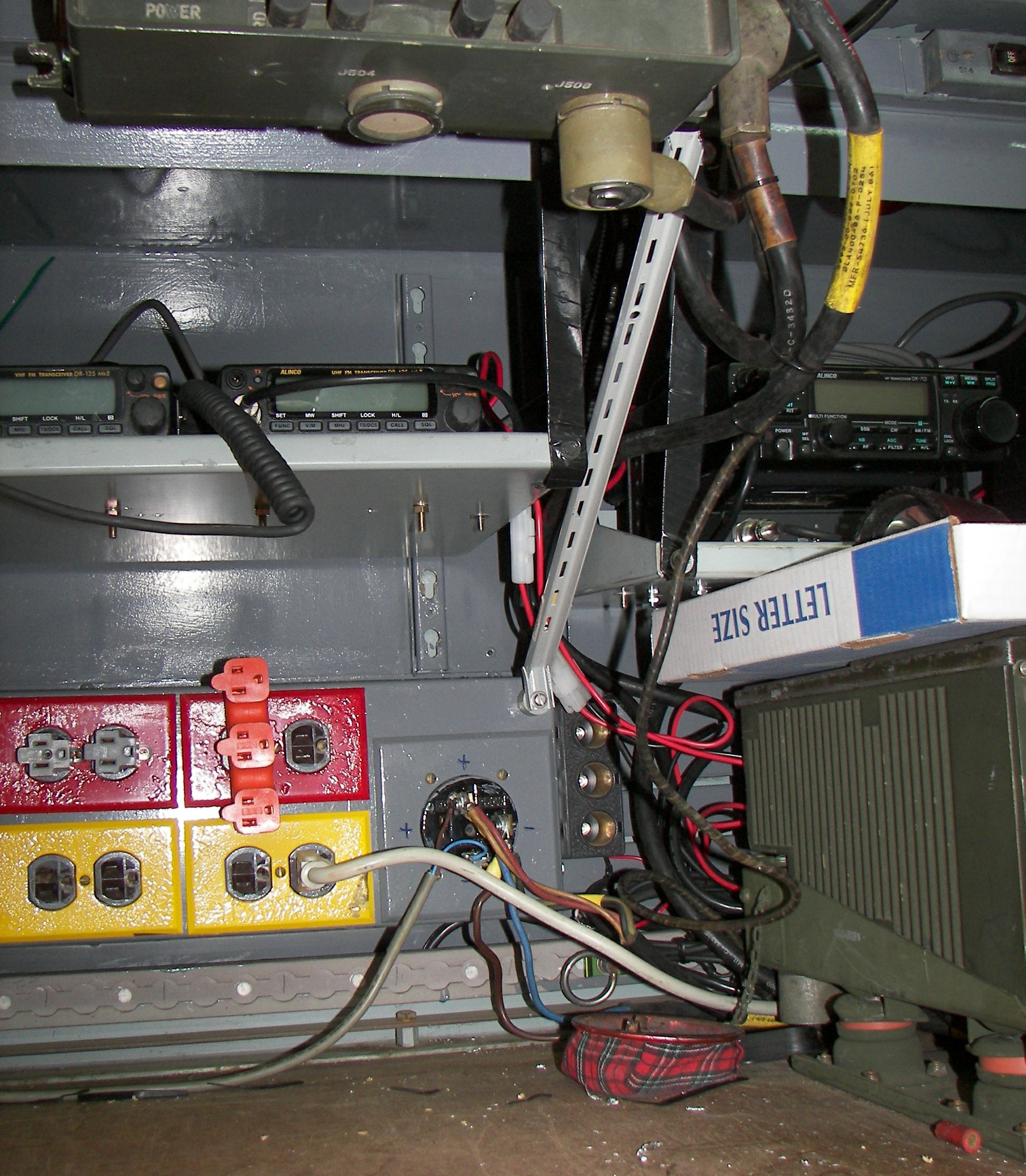
Close-up of the actuall connection made from the switched side of the breakers to the 24VDC shelter system. The shelter is wired for 100A 24V service, and these large sockets are rated for 50A continuous duty per pole. Two are positive, two negative (GND). The reason that there is no 'plug' on this is because the type, once used for ovens, welders, and 3-phase AC equipment, is obsolete now. A universal plug kit made for ovens and ranges consists of the proper blades to fit this socket, but the plug body will not. I don't have a facility to make this into a special plug. Later I will heatshrink the exposed places and we'll just have to keep any 'geniuses' from re-arranging the polarity. I am not worried about idiots, they will generally fear this arrangement on sight. The incoming ground wire (black) goes to the negative blade. This bus is bonded to the shelter body inside the power control panel at the rear of the shelter. The small wires shown go to the VIC-04 intercom's amplifier assembly, the 'brain' of the system. |

A good image of the Rockwell logo was in order.. |
view from the front, looking back along the right side of the shelter. |
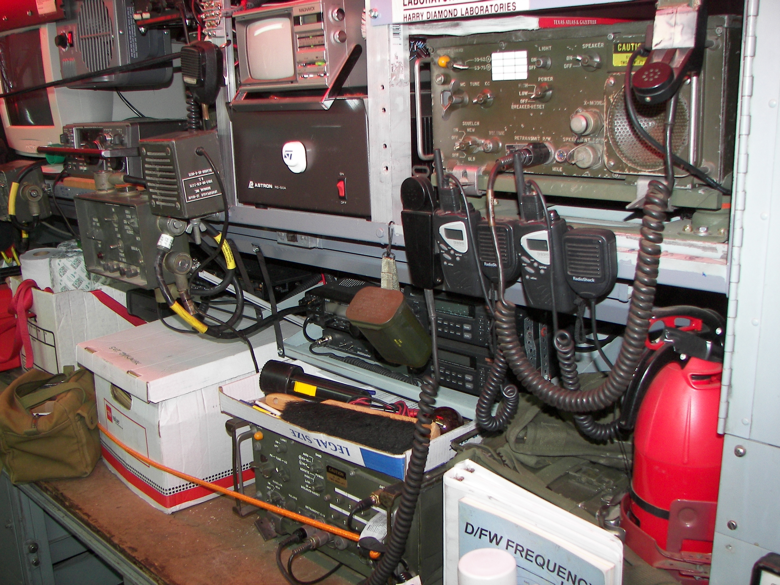
view from the rear, looking forward along the right side of the shelter. |
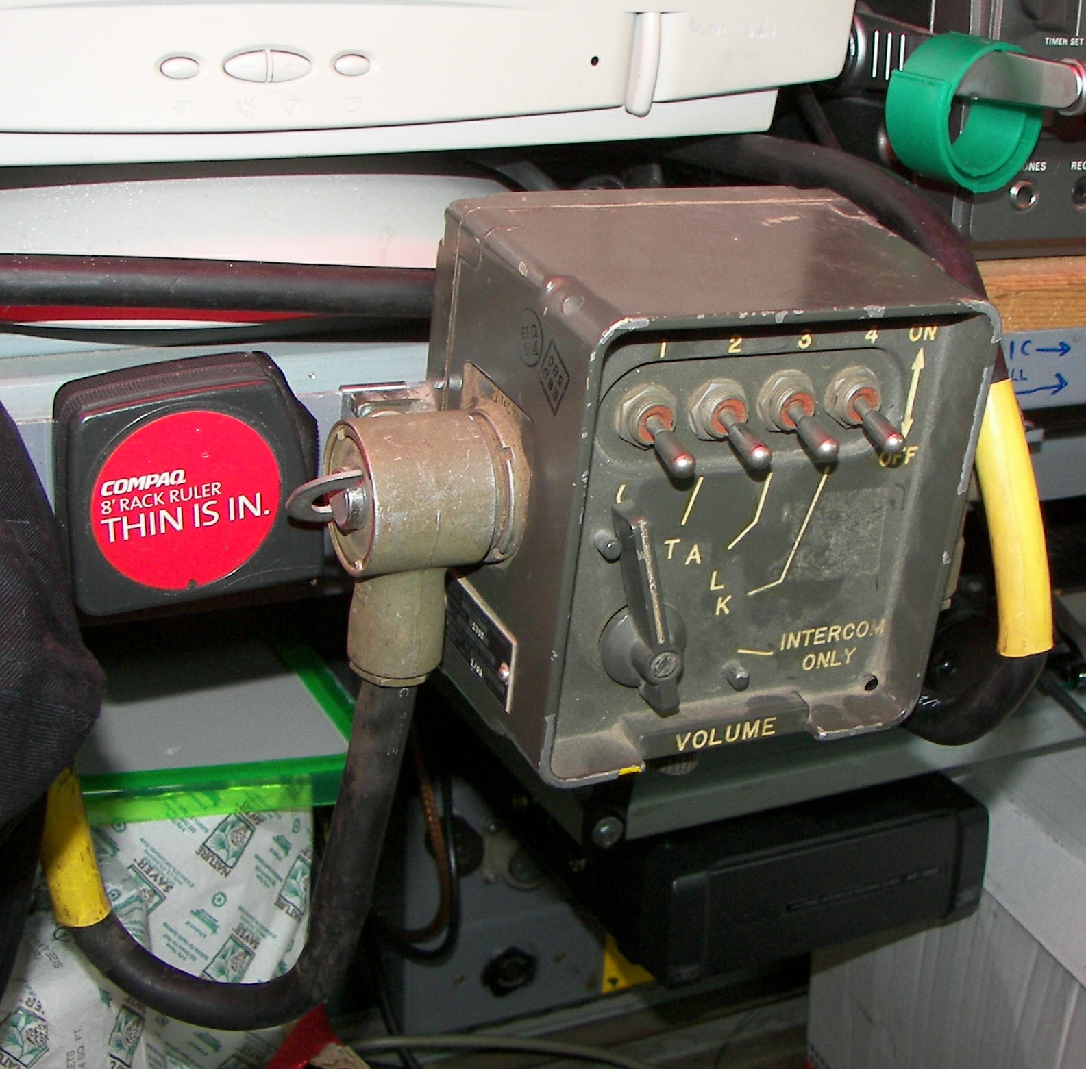
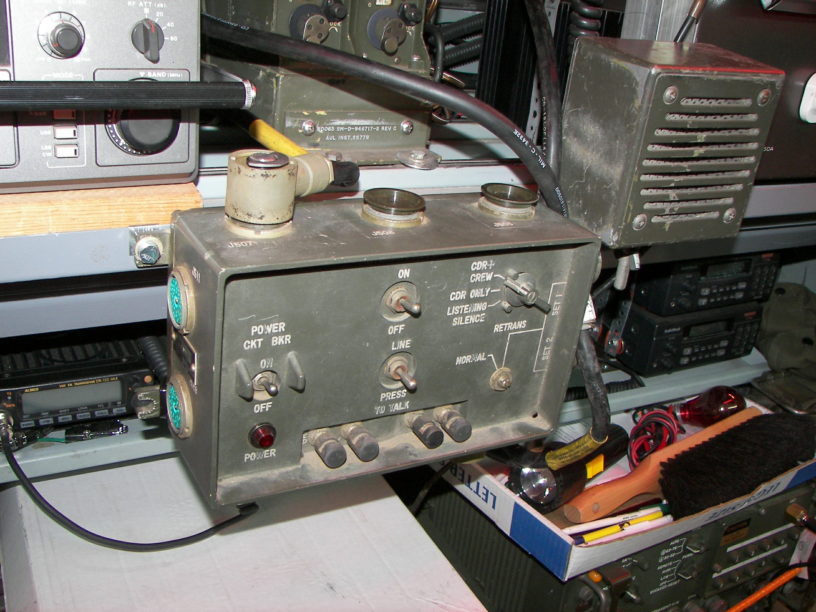
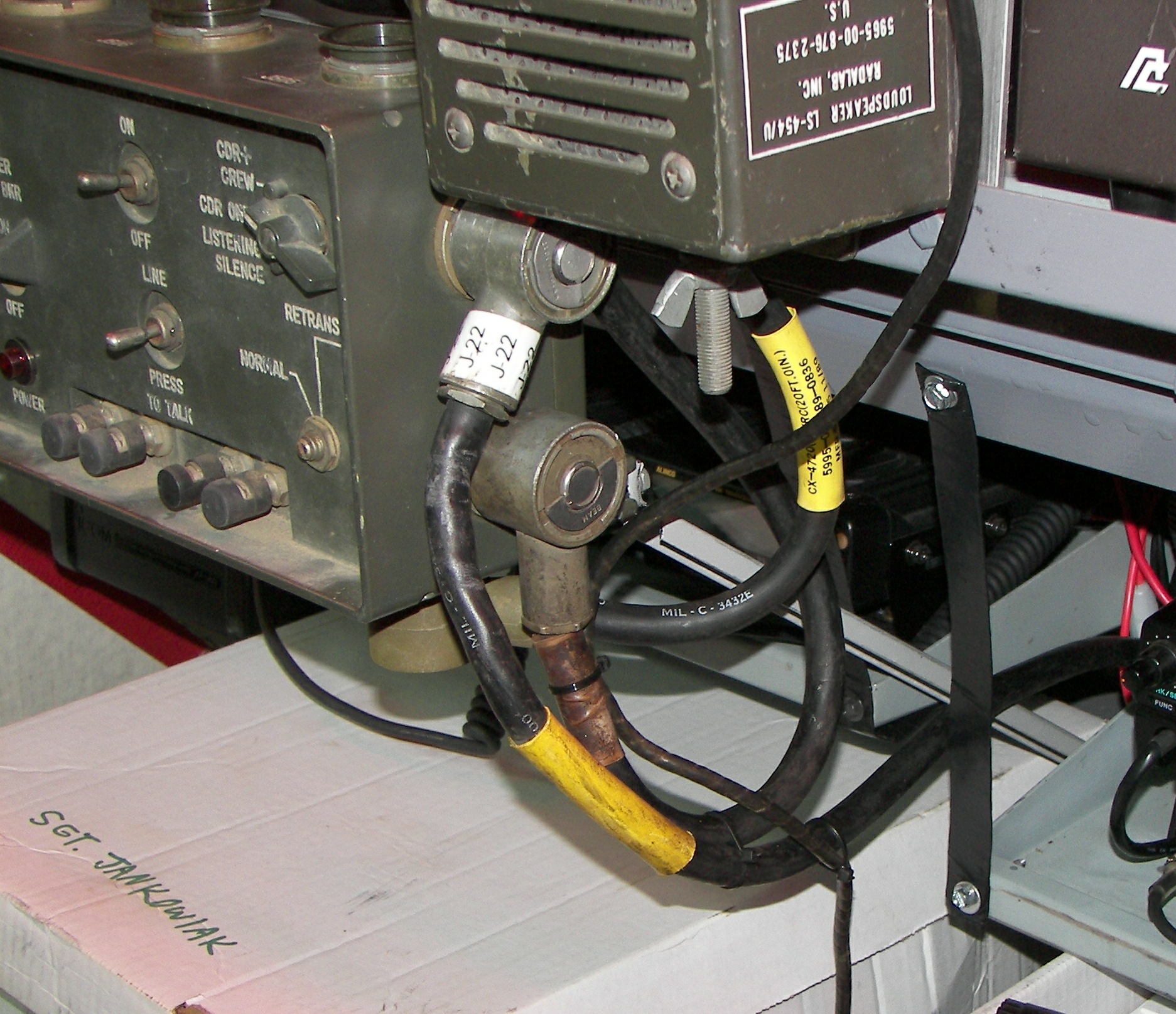
crew box. The cable from the cab connects to one side, and the cable to the amplifier connects to the other side. (this can be handy if your cable does not reach and you can't get a long enough one, just add a crew box. It does not have to function as long as the plug connections all still feed straight through.) Any of four tranceivers may be operated by a VIC-4. In contrast, The VIC-1 handles two tranceivers and two receivers. A modified version of the VIC-1 handles three tranceivers and one receiver. |

To mount the crew box and the amplifier unit, clip-on 1/4-20 'cage nuts' were installed. A flat washer and lock washer are a must in this high-vibration environment. |
The VIC-4's 'brain', the amplifier unit. The VRC-12 radio components (RT524, RT246) can be turned on and off remotely with this unit by changing a jumper in each of the radio mounts themselves, but I have chosen to leave the radio power manual, so that the radios can be operated independently of the VIC-4. |
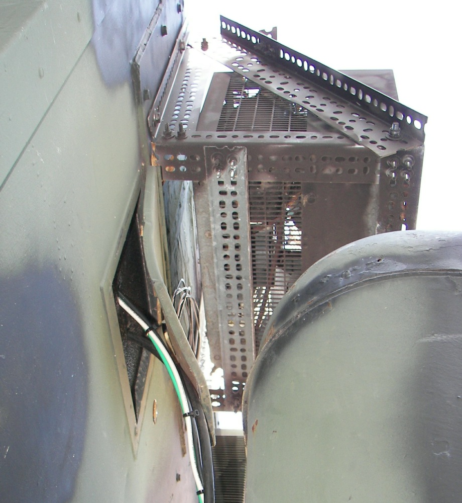
A brace was made to secure the bottom edge of the amplifier against vibration. The thin lip of the shelter's equipment shelf is adequate for the weight but not for the constant vibration which would crack the aluminum lip over time. The brace was made of the slotted C-channel-like material used for mounting shelving on a wall in a house. It can be brittle, but if cut and bent carefully is durable enough. |
The brace conveniently passes between the radio shelves back to the power panel. Originally there was a rubber bumper machine-screwed to the panel, but it was removed. Note the black supports on the radio shelves. It was learned the hard way that the rear corners of the shelves can crack due to vibration with the radios in place. The supports were made of perforated metal duct-hanging strap covered with electrical tape and have held up very well. |

Below the desk area is a set of four 12 volt 95 amp-hour AGM batteries. These will be put in series and become part of the shelter's 24V system, with a tap at 12V which will be connected to the shelter's 12V bus which was added on to operate the commercial radio equipment. The shelter itself has provision for a 100A 24V power supply and this is where these batteries come in. They will be on the back side of the shelter's original 100A circuit breaker and ammeter. When the aux power switch in the cab is turned on, the batteries will be in parallel with the vehicle batteries and will be charged if the vehicle is running. There's a little electrical wiring left to do here and a method of safely mounting the batteries has to be devised. |

view from the front, looking back along the left side. The green cabinet is a 4FT rack with a complete 100W UHF repeater in it. I am going to get rid of the repeater and keep the cabinet. Further to the back is a little microwave oven, er.. radar test set. Comes in handy. |
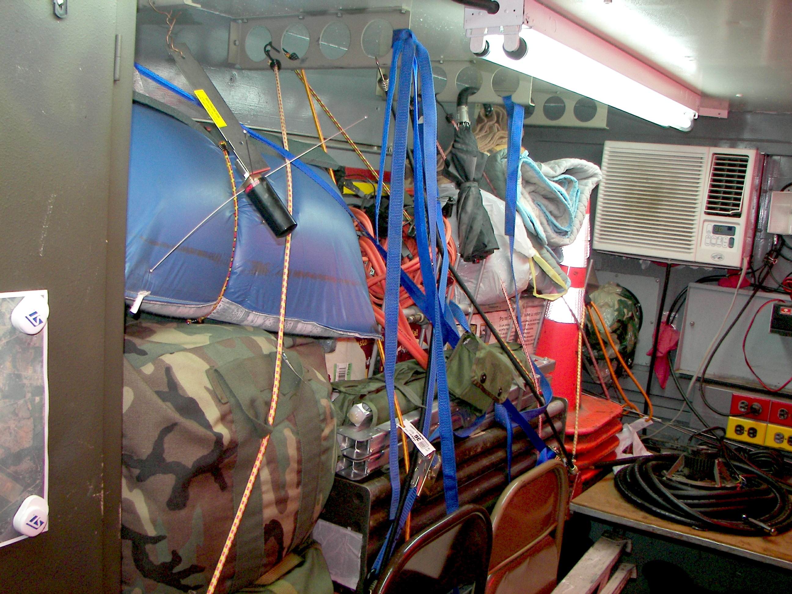
This mess is more organized than it looks. two duffle bags and a nice thick bedroll, a cot, two 40' AB-56 mast kits, various mast mounted and magnet mount antennas, VHF, UHF, narrowband, broadband.. a pavillion tent, jumper cables. some traffic pylons. Shelving with retaining bars will be put in place here to get rid of the mess of bungees. |
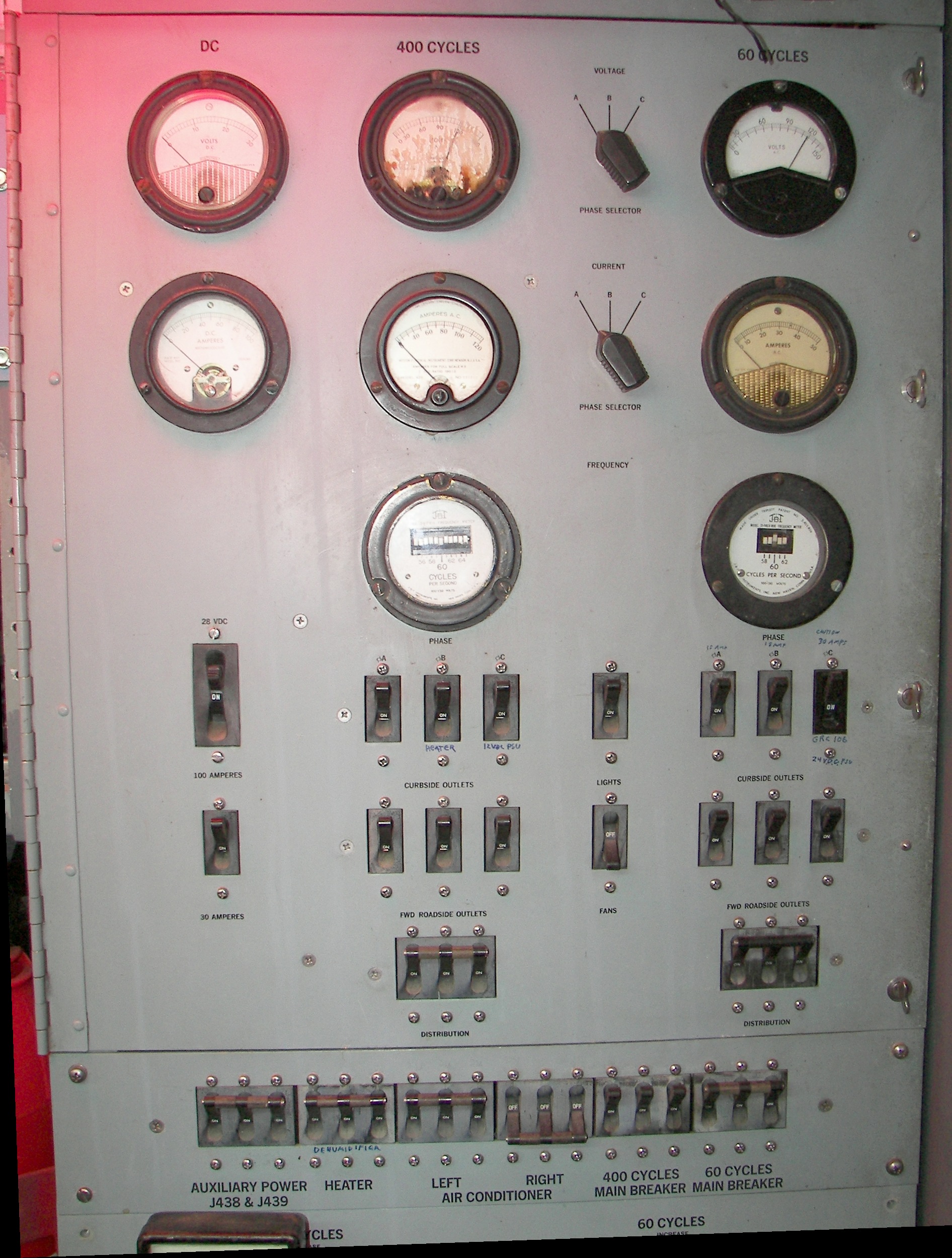
The power control panel is really the centerpiece of the shelter itself. Originally, there were two 3-phase 50A inputs, one for 60Hz and one for 400Hz. Each phase is individually meterable for voltage and current. Both inputs have a f\vibrating-reed type frequency meter. This panel is great when you have a crappy generator and the vendor argues. Stops all discussion right there. The argument over whether the generator is working properly or not, it stops at that panel. I was at first concerned about the discoloration of a couple of the insides of the meter glasses, but it is just a preservative grease-like substance that has flowed somehow. Maybe the shelter got dumped on its side at DRMo for a few years, who knows? |

The square guage is an old pressure cooker guage.. it fit the hole, so.. and it shows me if it's 80 or 100 or 120 degrees inside. The air conditioning system keeps it below 80 and above freezing and maintains the humidty at less than 50%. |

The dehumidifier works well. It's airflow path was modified and it now sucks in air from the back and exahusts it from the front. Despite there being no side panels, a smoke test shows that it does draw air substantially from inside the panel through the grille at the panel top. Humidity tended to build up in there for whatever reason. The drainage issue had to be worked out. A catch pan was made from an antifreeze jug and a fitting glued into it. the fitting connects to a clear plastic hose just visible on the lower right. This hose exits through the vent/drainage plug in that corner of the shelter right in front of the power rack. A small electricians' junction box protects the hose as it makes a 90 and heads downward. The wire ties on the hose help keep it round so that it does not get lazy and collapse. Above the dehumidifier is a grille with a knob. That's from an old radio set, and can be opened, if you want to stow something small and non-conductive in there. In the past, a 24V 100A power supply had been mounted there, but it was cooked. |
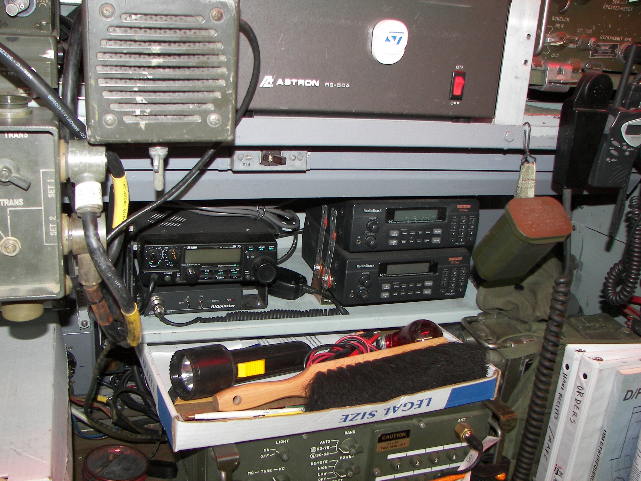
View shows the 12V 50A power supply up top, the RT246's speaker, under that, an Alinco DX-70 HF/6M tranceiver and two scanners on a shelf, and the RT246 underneath. A PRC-77 is stashed to the right, along with a 12V amplified speaker and power supply cable (Haney Electronics). This can go on the ATV or in a vehicle when things get deployed. |

The shelf to the left of the other shelf.. an Icom IC-706, and an Alinco DR-135 and DR-435. I prefer the Alinco units. the controls are intuitive, and they can be connected as a crossband repeater simply by plugging a DB-9 cable between them. Under the shelf is the automatic antenna tuber for the IC-706. The HF radios (two plus the Kenwoof R-1000 receiver) are by default run through a selector switch and to the bumper-mounted HF antenna. |
 The top equipment shelf holds, from left to right, space heater and Kenwood R-1000 HF receiver, public address system (black and red box), and diplexer for the VRC-12 gear. Then a small TV set and the 12V power supply, and part of the RT524 can be seen. The cable on the top of the VIC-4 is from the string of crew boxes. The side cables are to tranceivers 1 and 2, the VRC-12 components. Two ports are available on the left side for two more tranceivers. I will probably connect a CB radio to one of them for road use and add a tuner to make use of the 9 FT bumper-mounted HF whip. The top equipment shelf holds, from left to right, space heater and Kenwood R-1000 HF receiver, public address system (black and red box), and diplexer for the VRC-12 gear. Then a small TV set and the 12V power supply, and part of the RT524 can be seen. The cable on the top of the VIC-4 is from the string of crew boxes. The side cables are to tranceivers 1 and 2, the VRC-12 components. Two ports are available on the left side for two more tranceivers. I will probably connect a CB radio to one of them for road use and add a tuner to make use of the 9 FT bumper-mounted HF whip.
|
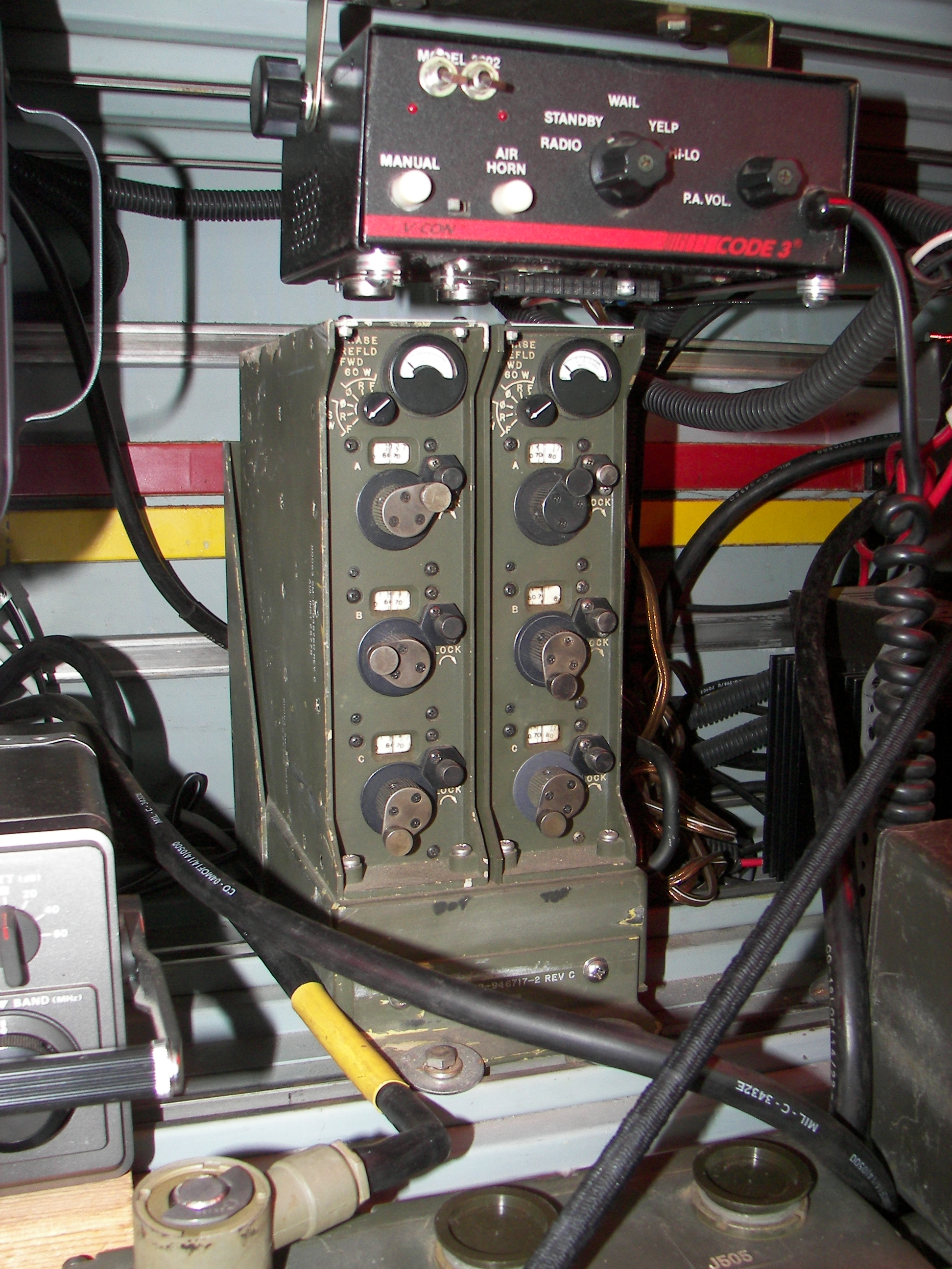
close-up on the diplexer. Each bay is separately tuned for the radio connected to it by means of three controls. A meter shows the forward and reflected power and the phasing. Proper tuning gives a null when the switch is set to phase. This allows both VRC radio to be used at the same time on the same antenna as long as the frequencies are separated by a certain amount. The diplexer feeds the VHF bumper-mounted antenna. It's a boradband type used for SINCGARS and needs no auxiliary tuning cable nor has a switch. I have been thinking about getting a 5-bay unit since the Alinco has a 35-65MHz capability on its "6-meter" side. Yes all the radios in here are 'opened up' to be able to transmit on any selectable frequency (just like any good military radio!). It's up to the operator to use the authorized frequencies. |
Something is missing.. I removed the GRC-106 tranceiver. Since I had already two HF radios and need the space for two computers to use for data transmission, the big 400 watt radio and its 24V 50A power supply had to go. |
Page 3 of 4