Preliminary Manual 253MB PDF file including above schematic
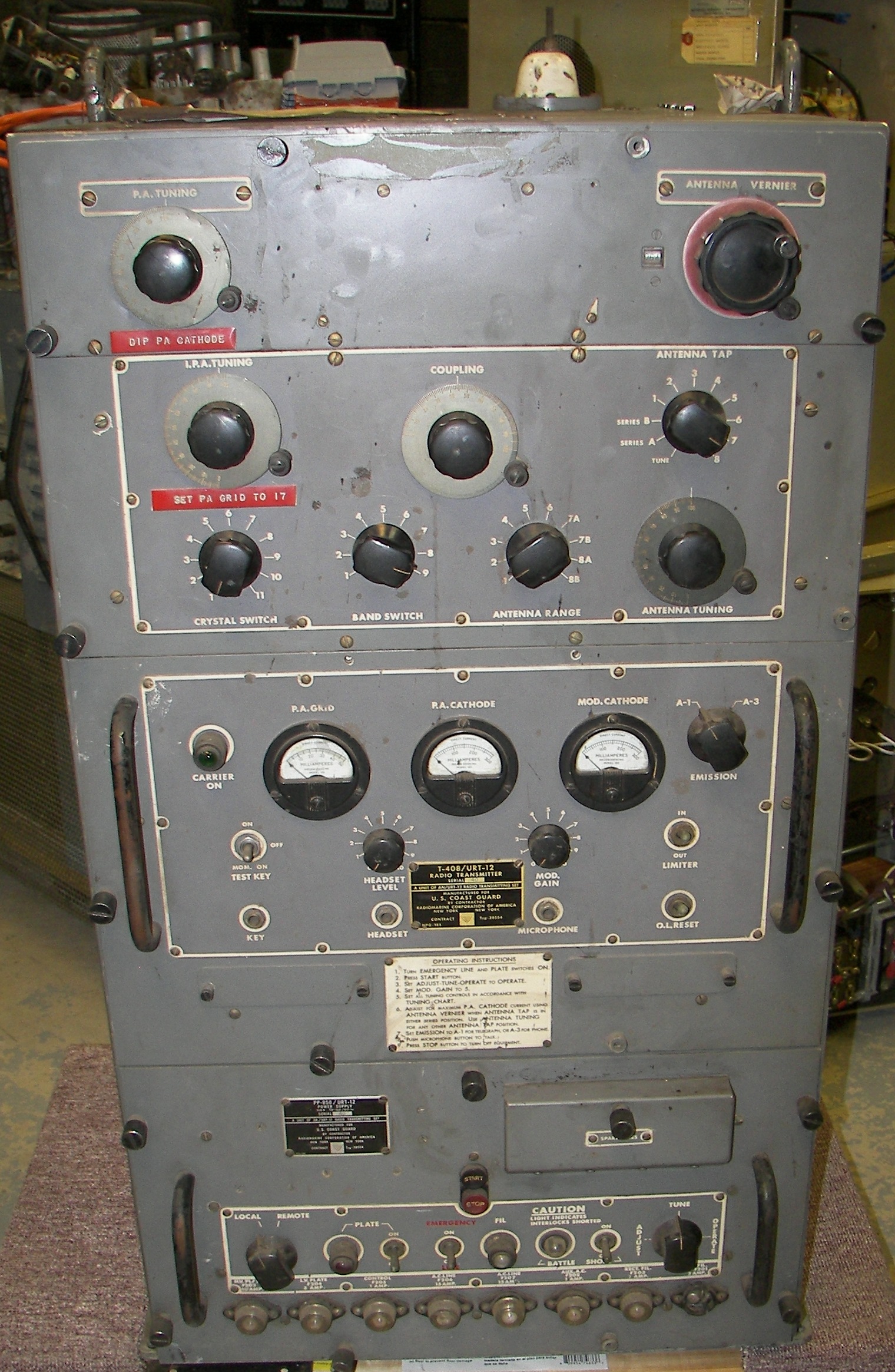 971.34 Kb 1520 x 2329 Front view |
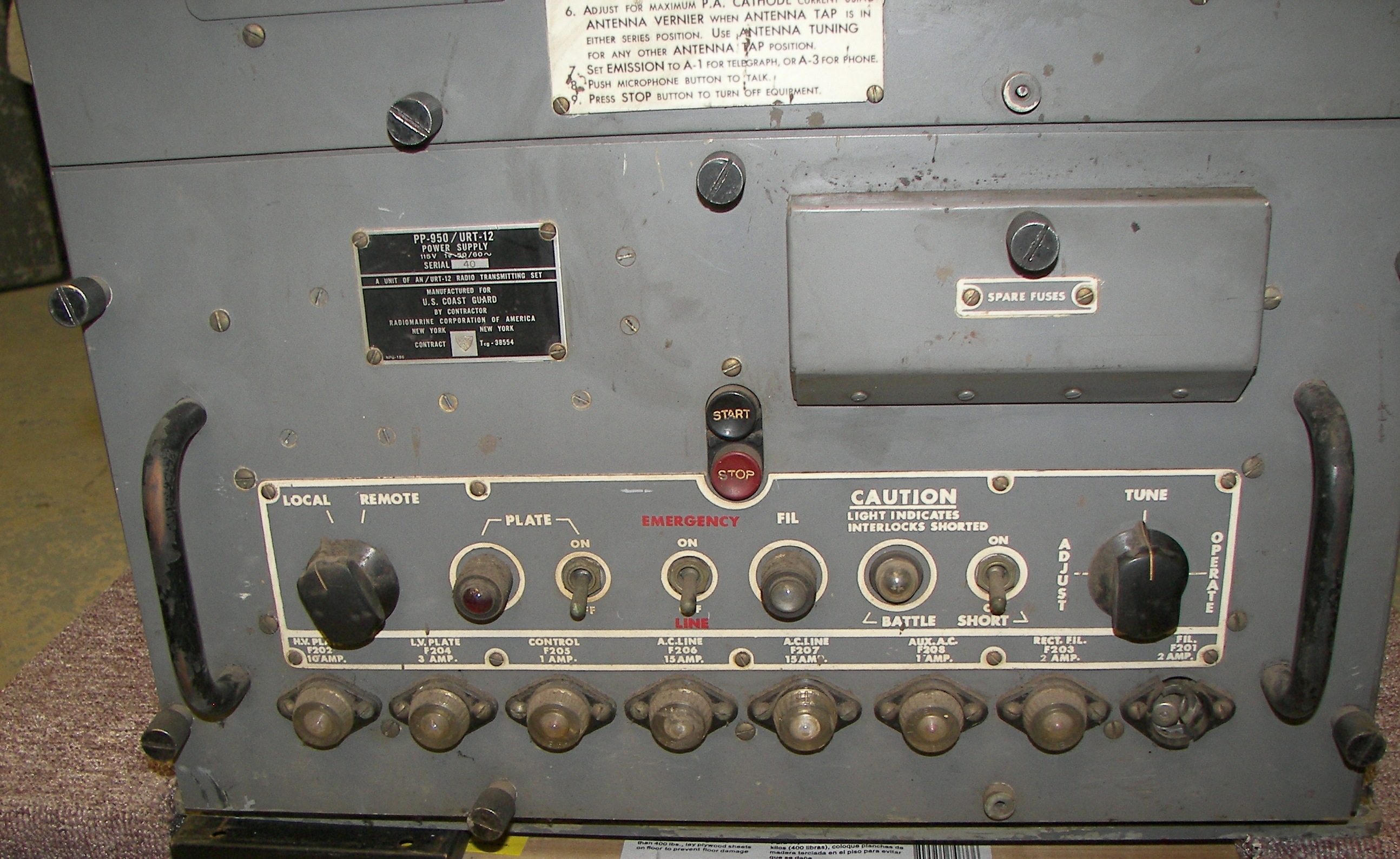 1071.07 Kb 2588 x 1588 Power supply unit |
 990.77 Kb 2583 x 1534 Metering panel |
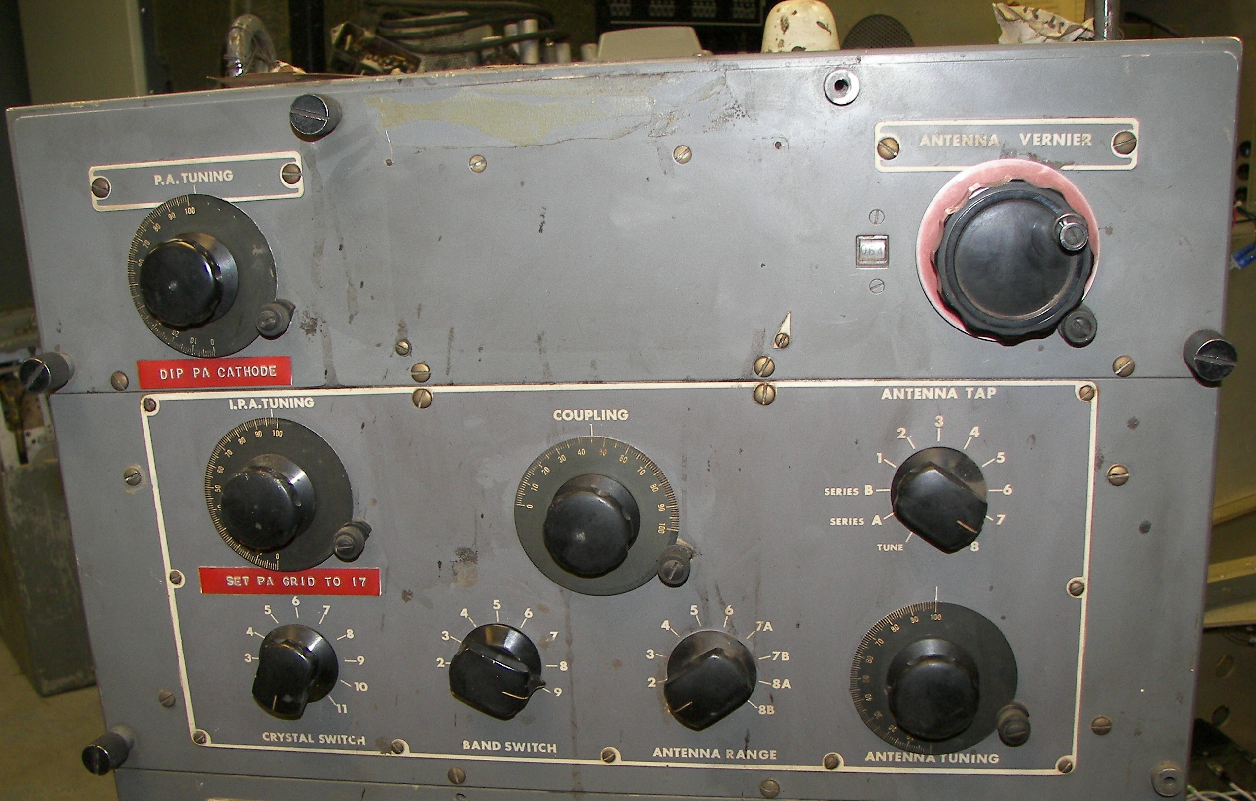 996.67 Kb 2547 x 1624 RF tuning controls |
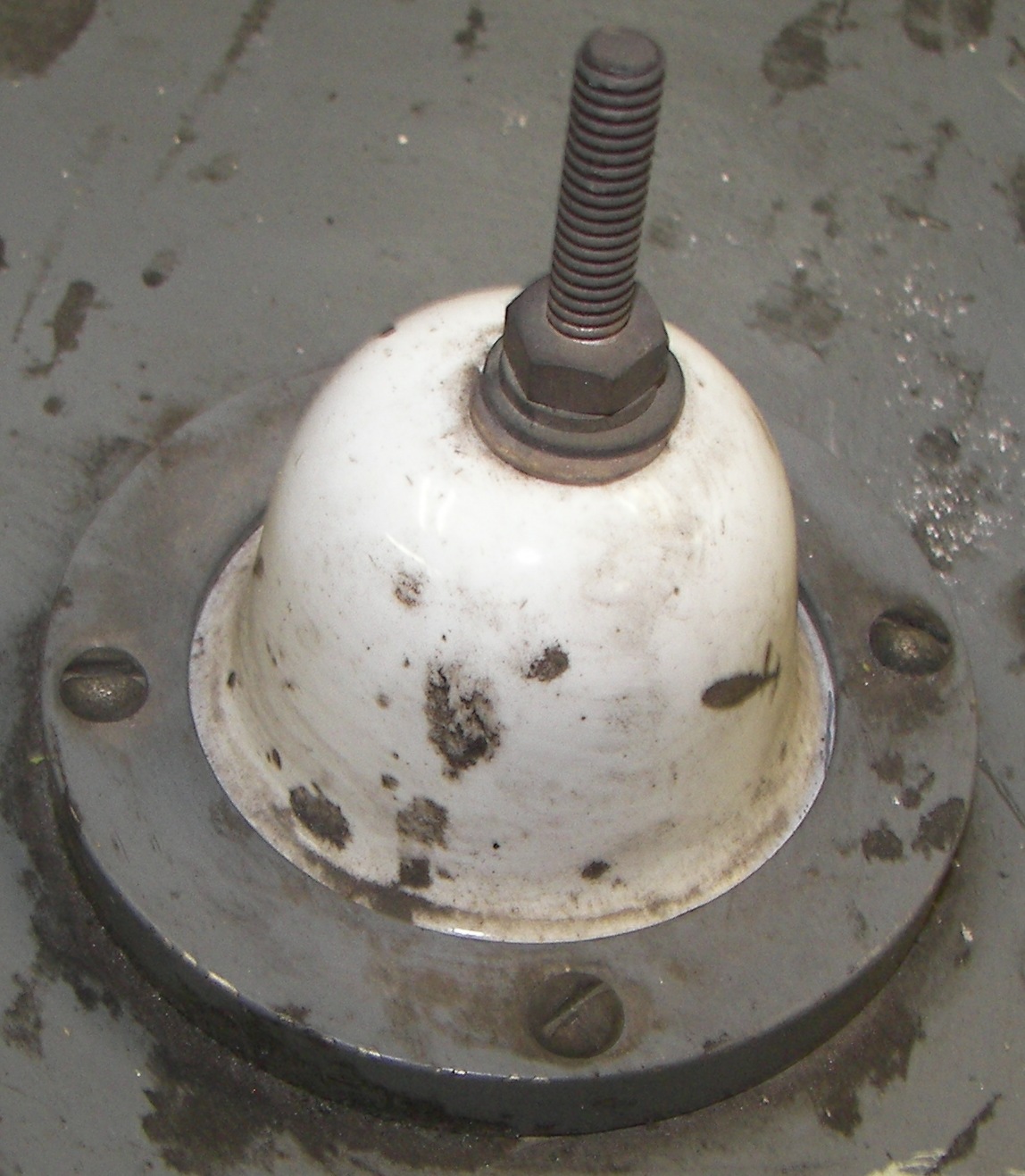
 1183.66 Kb 2592 x 1696 Top of unit with classic insulator. This would connect to a long wire antenna. |
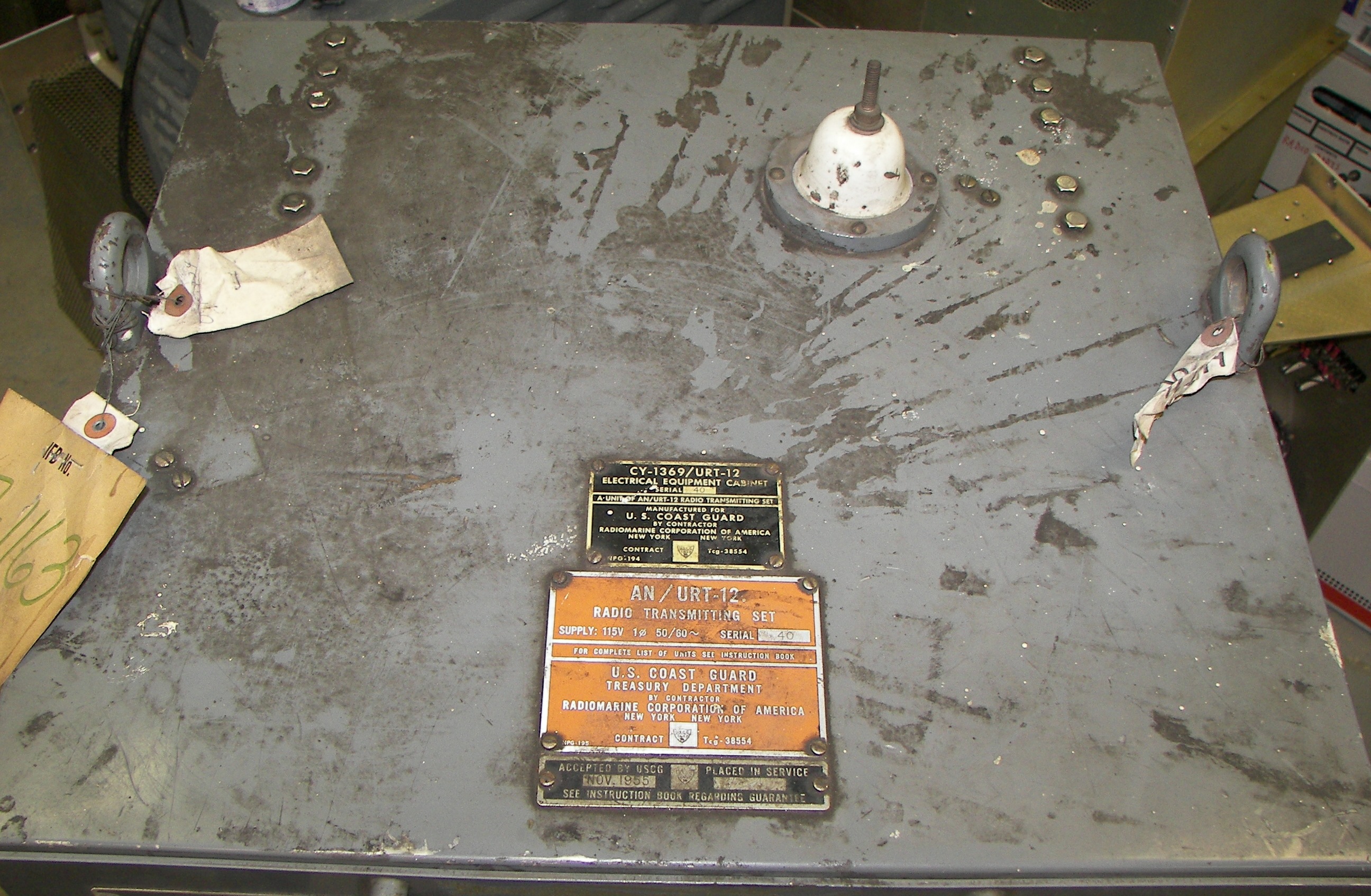
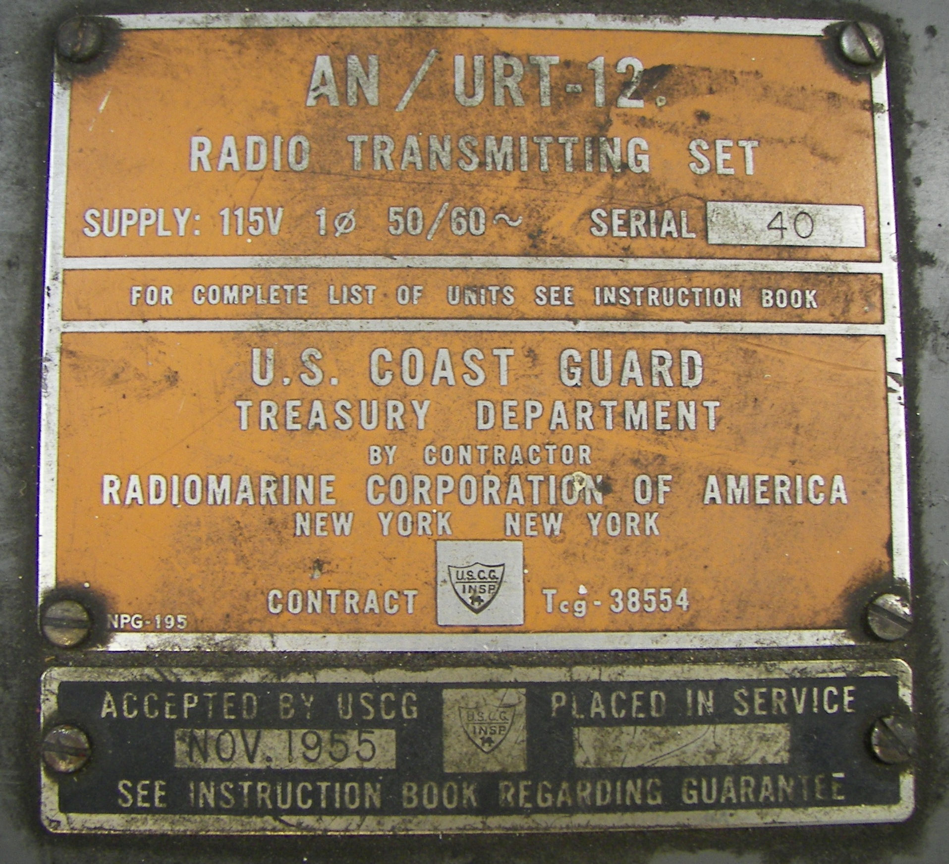 953.58 Kb 1915 x 1743 Nomenclature tags |
 310.27 Kb 1148 x 1317 |
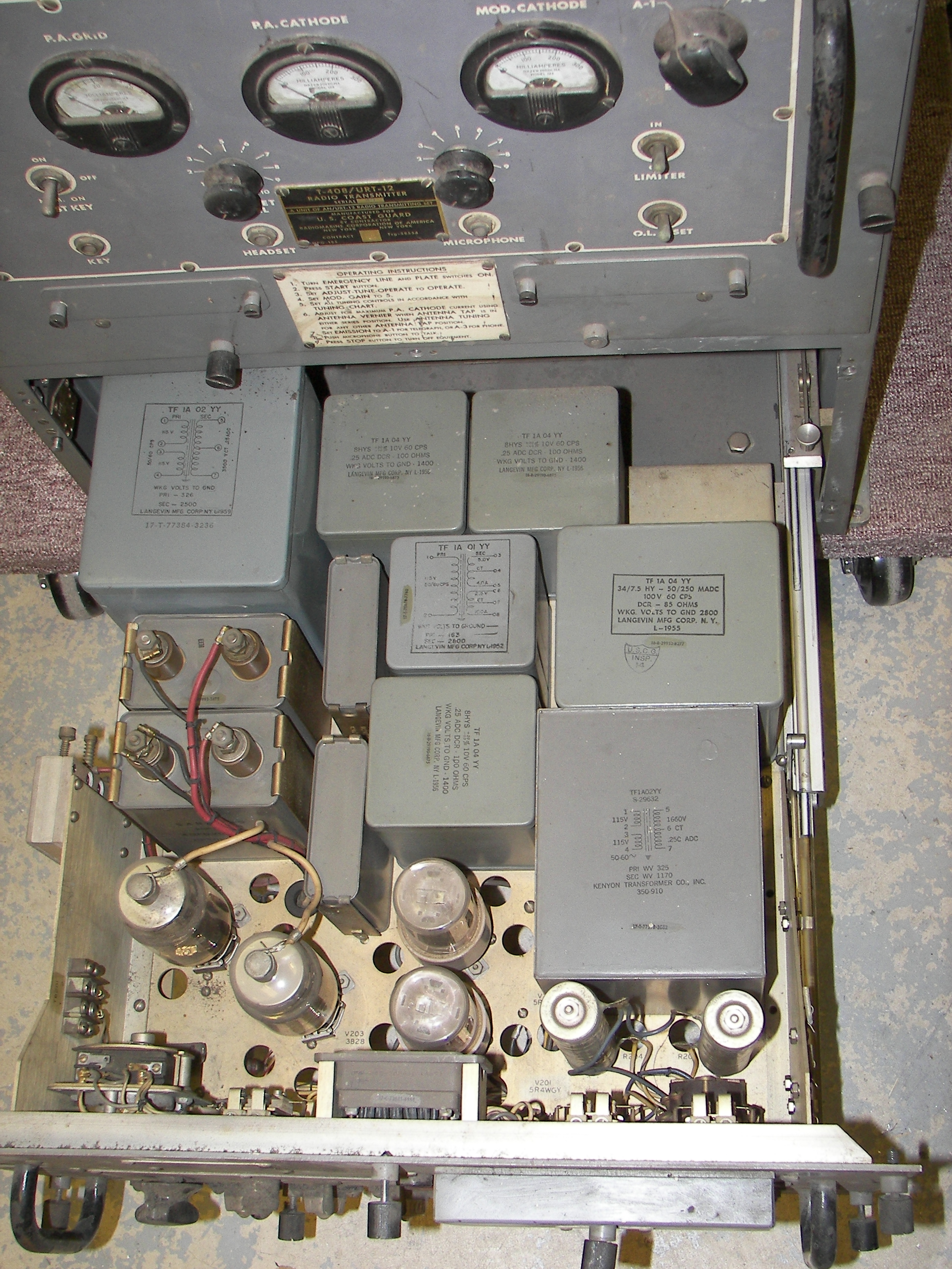 2.49 Mb 1944 x 2592 Power supply drawer. |
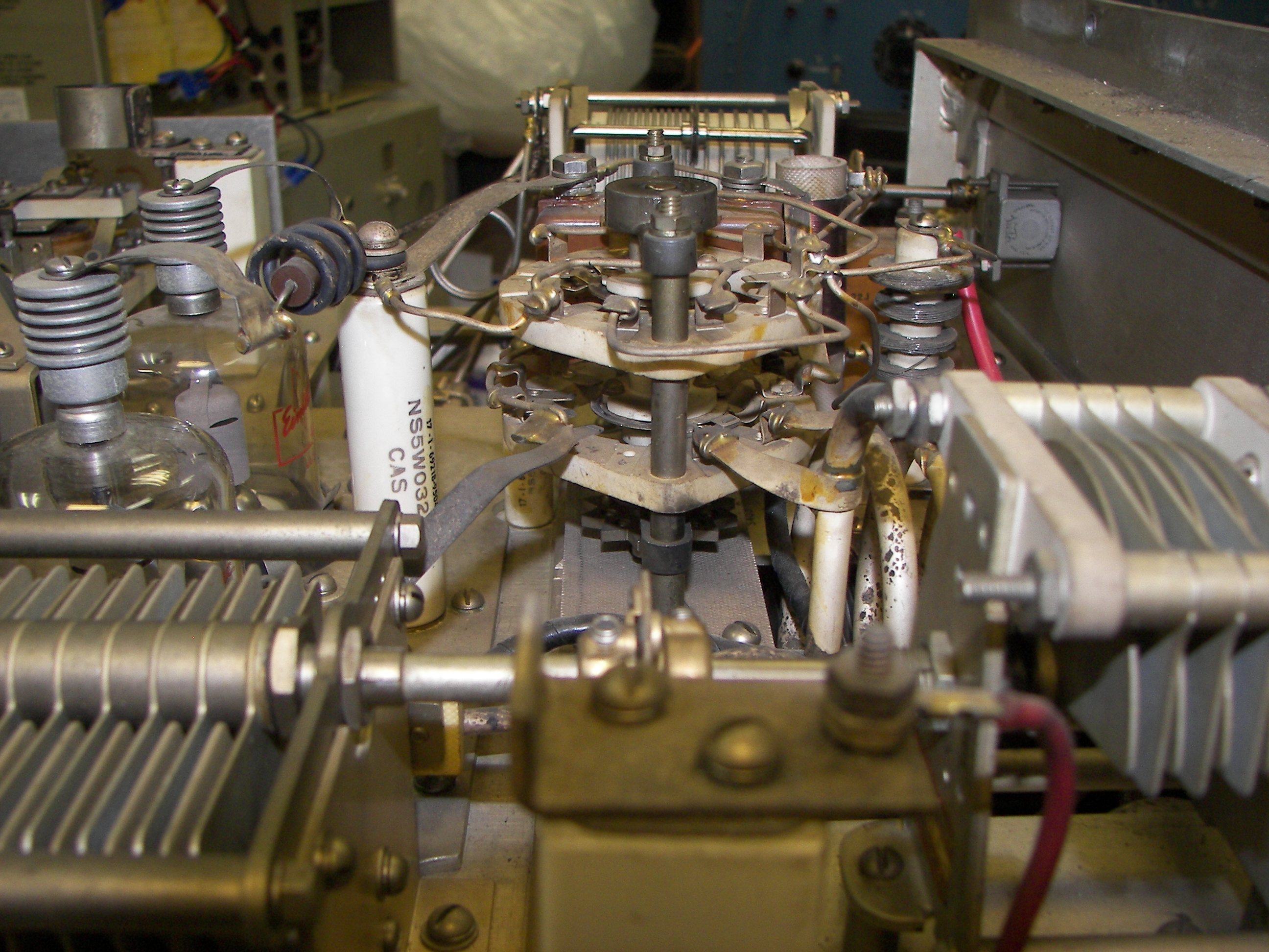
 1195.46 Kb 2003 x 1938 Top of RF deck. Variable inductor is part of antenna tuning system. PS tuning is at the top of the picture (left side of the unit). |
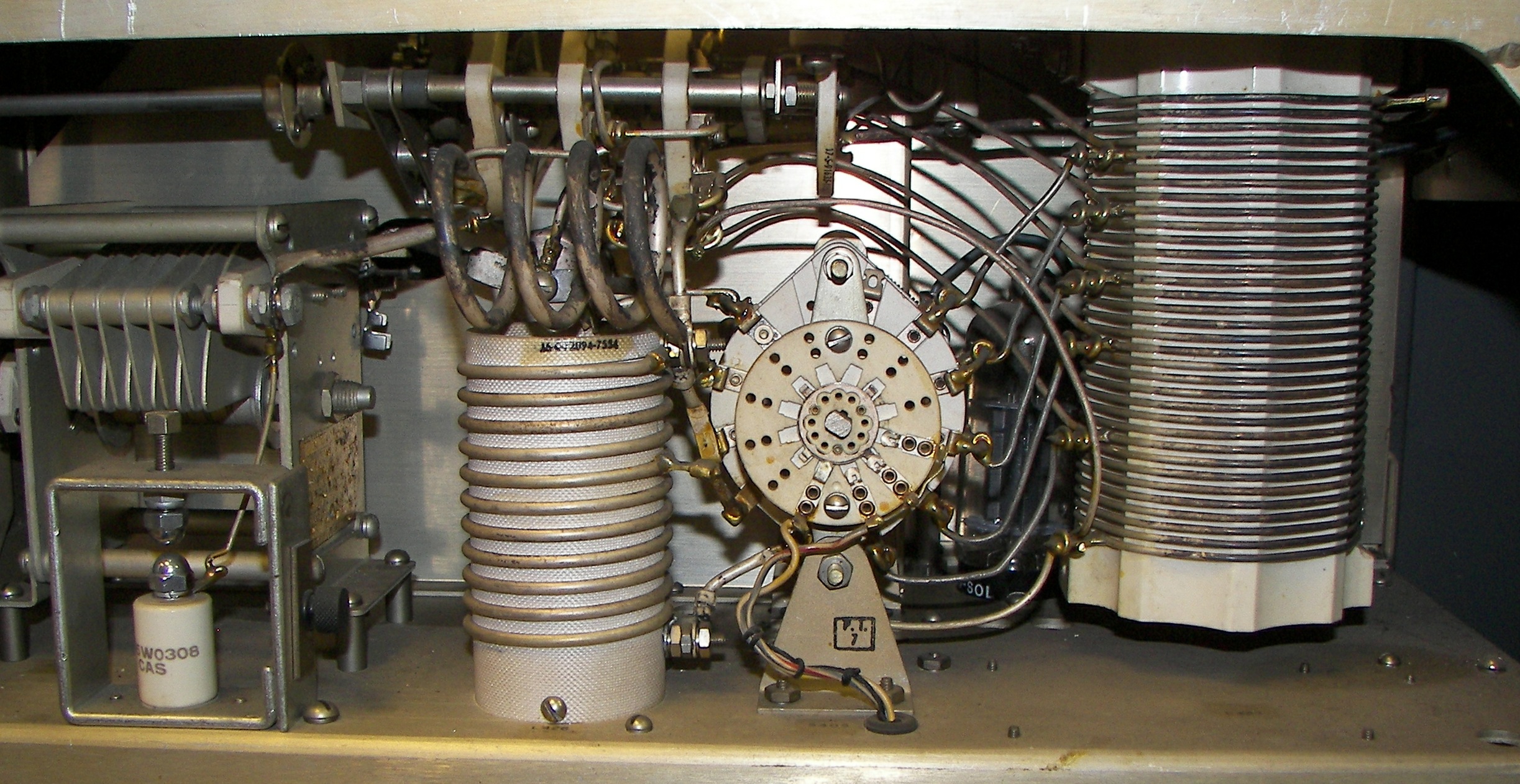 924.25 Kb 2446 x 1262 antenna tuning components directly under final RF deck |
 758.59 Kb 2458 x 1245 Modulator section (under antenna tuning section). The large transformer to the right (rear of unit) is the modulation transformer. |
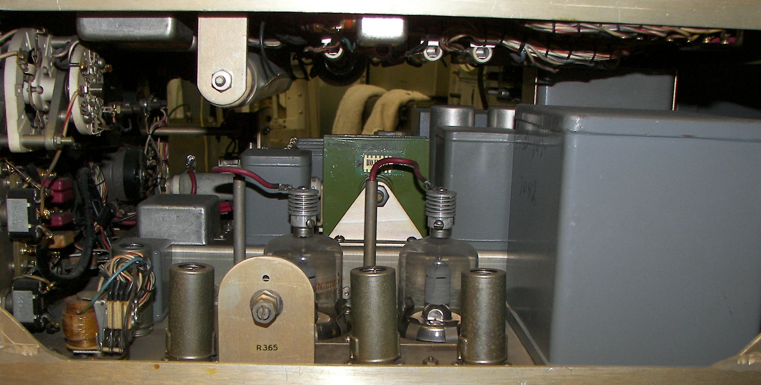
 957.05 Kb 2576 x 1369 IPA (driver) section uses an 807. To the right in the picture (rear of unit) is the crystal oscillator assembly. |
 1048.53 Kb 2554 x 1553 Power components in RF section. Control relays are to the right (front of unit). |
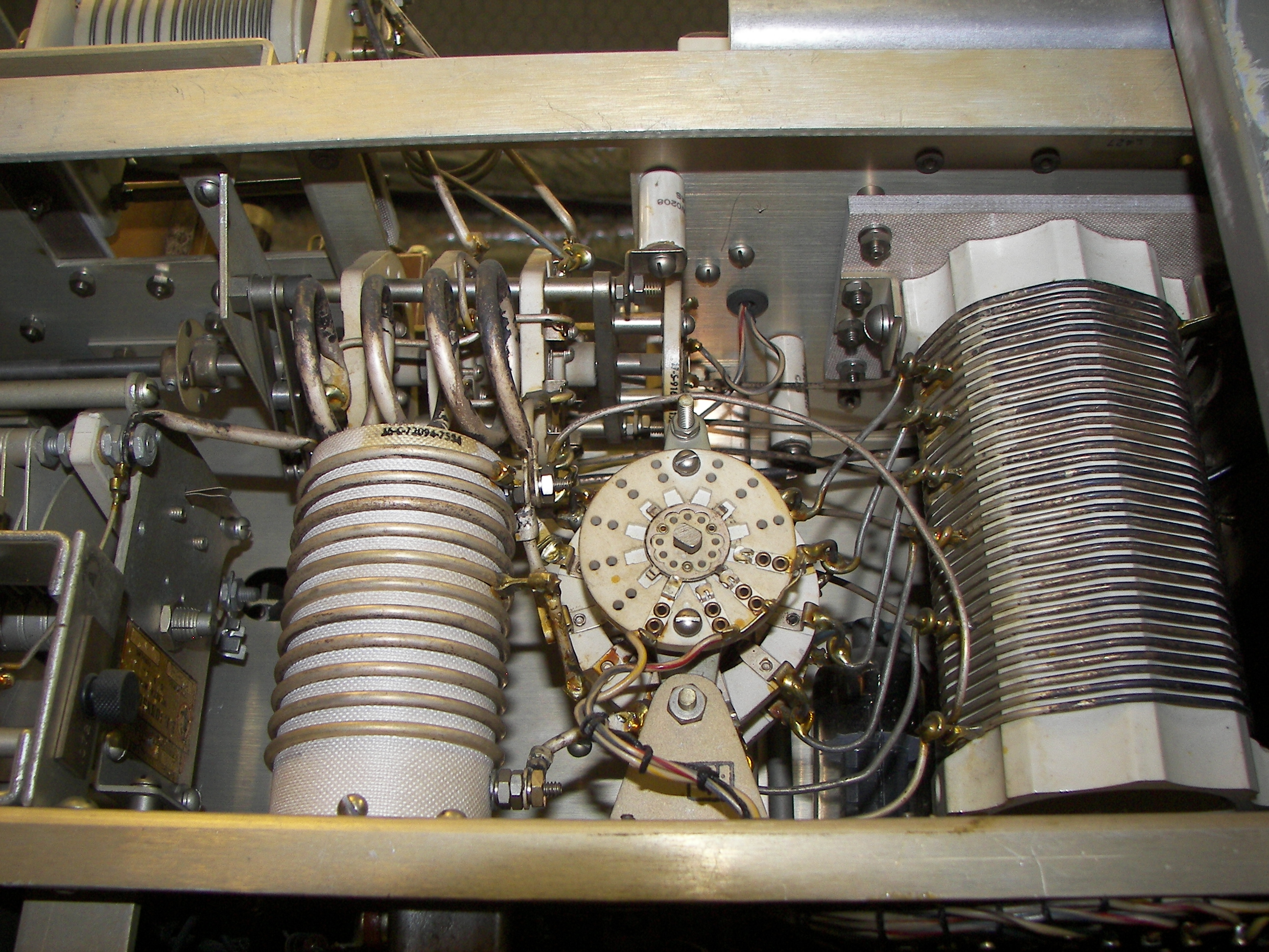
 2.31 Mb 2592 x 1944 Crystal (channel) selector |
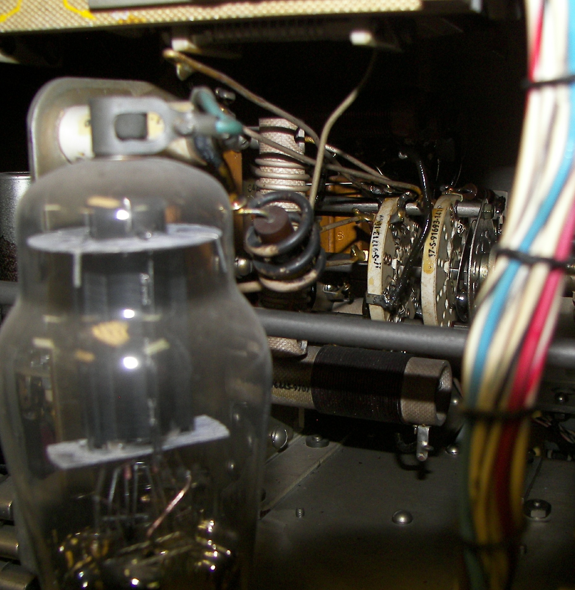
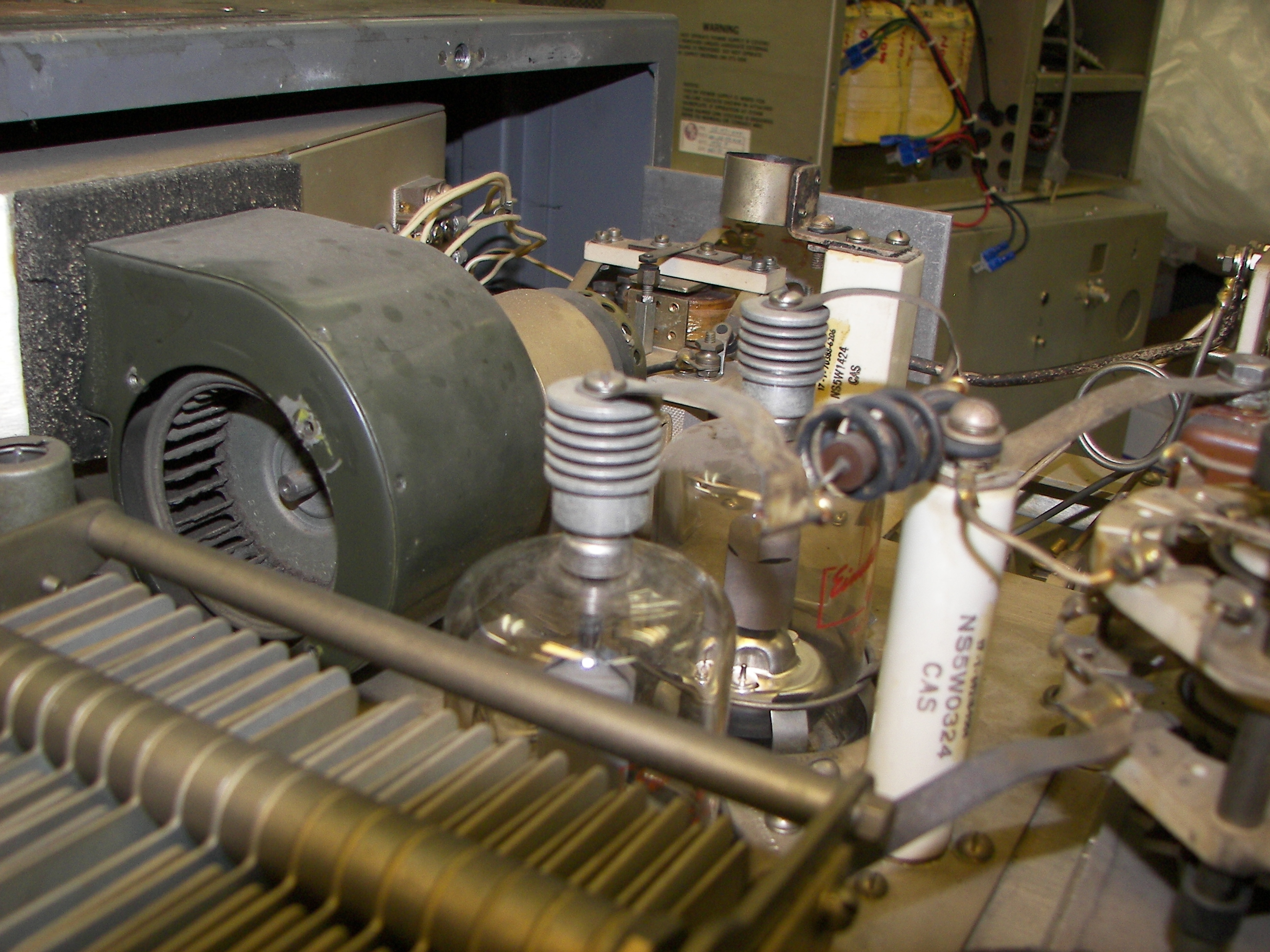
 810.75 Kb 2209 x 1654 tubes near the crystals, perhaps the oscillator and buffer. |
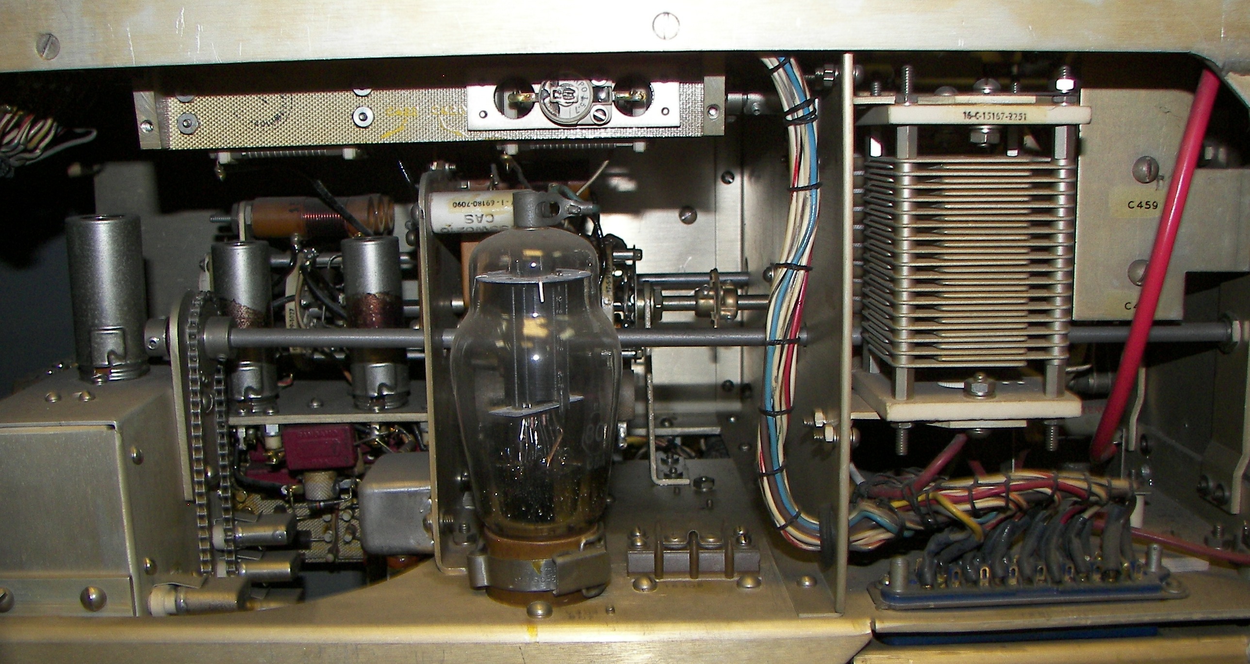
 739.70 Kb 1860 x 1908 IPA (driver) tube circuits. |
 2.09 Mb 1944 x 2592 control relays |
 2.34 Mb 2592 x 1944 side view of final RF deck |
 2.28 Mb 2592 x 1944 RR deck showing blower and PA tubes. |
 2.45 Mb 2592 x 1944 Part of the antenna tuning unit. There is a much larger switch behind the small wafer. |
 2.75 Mb 2592 x 1944 Another view of the tuning unit. In the very back can be seen what looks like a 6CD6 or 6BG6 tube. |