The first thing to consider with a white LED is the operating power. The voltage is a bit higher than other LEDs, about 3.5VDC. The current is typically 20 mA for full lifetime. beware increasing the current to get more light, as this will (with any LED) reduce lifetime. LEDs last about 10,000 hours at the rated current.
Since the voltage is not quite standard, adding a resistor is the easiest way to make the LED work with whatever DC voltage you have. If you have more than about 4 volts for your supply you can use a white LED very simply. If you have a high voltage such as 24-28 volts, several LEDs can be wired in series and only one resistor is needed for the chain.
Q. OK, how many LEDs do I use for "X" volts?
Q. I have figured out that I need 5 LEDs, and the supply voltage is 24V. If the LEDs each use 3.5V, it only adds up to 17.5; What do I do here?
Remember -the resistor is what limits the amperage through the LEDs and keeps them from burning out. If you were to just strap 7 or eight 3.5V LEDS across 28VDC, they'd blow instantly. The amperage has to be limited, just like a flourescent lamp needs a ballast. This is why, in the previous step, I divided by 4.5. I am counting 4.5 volts of supply voltage for each LED because it's necessary to arrive at a reasonable value of resistance so that small variations in power supply voltage won't cause large variations in LED current.
Q. Ok, so now that I know I need to lose 6.5 volts in the resistor, how do I know what value of resistance to buy?
A. An LED of the type shows here (typical) works best with 0.02 Amps (20 milliamperes) of current. Do this math: voltage divided by current equals Ohms (resistance). 6.5/0.02=325. Use a 325 ohm resistor. A 300 ohm resistor may be easier to get, and will pass 21mA, which is ok.
Q. The guy at radio shack said that resistors come in different power ratings. I don't want to use too small of one or it will burn out. Which one is right?
A. This is simple too. Wattage is determined by multiplying the voltage by the current. The resistor with 6.5 volts across it and 0.02 Amps flowing through it will dissipate 0.08 watt. You can use a 1/4 watt size (0.25W) for plenty of safety margin. It's important to slightly oversize the resistor, since resistors can change value if they get too hot.
Q. I'm putting this inside the dome light in a military vehicle. When the vehicle is running, I have 28VDC instead of 24V. What effect will this have?
A. Since the voltage across the LED is pretty close to 3.5 over a wide current range, the stack will still be running about 17.5V. The 300 ohm resistor will now have 10.5 volts across it, and the LED current will be 0.035 Amp (35mA). This is way too much current. Increase the resistance a bit in order to limit the current to maybe 25mA max. 10.5 volts divided by 0.025A=420 ohms. A 450 or 470 ohm resistor will do fine. To get right on the proper current value, 525 ohms will give you the proper (conservative) 20mA at 28VDC. Figure the wattage the same way: 10.5*0.02=0.21 watt. Using a 1/2 watt size is ok. The LEDs will still light up very well at 24V when the engine is off, even with the 525 ohm resistor.
Q. What about AC voltage or polarity?
A. LEDs are definitely polarized devices. Light Emitting Diodes.. Use a bridge or other rectifier to provide DC for them. They will flicker unless a capacitor is used to filter the pulsating rectified power to smooth DC.
Here's a chart of common voltages, number of LEDs, and resistances to use. The more LEDs you put in series for a given voltage.
Remember:
A. The fewer LEDs you use, the less effect any variations in voltage will have on the current (brightness). The more you use, the more light you will get. Voltage divided by 4.5 equals a reasonable number of LEDs. You can go as low as "4" or as high as "6" with this factor. 24V/4.5=5.33 -You can't use 0.33 LED, so figure on 5 LEDs.
A. Each LED uses about 3.5V to operate, so figure that you will need 3.5 * 5, or a total of 17.5 volts across the LEDs -that's right. Your supply voltage is 24, so you need to subtract 17.5 from 24, to get the voltage drop across the resistor (24-17.5=6.5 volts). Exactly, you need to absorb 6.5 volts, but don't do it with another LED or two, use a resistor.
The more LEDs in series, the smaller the limiting resistance will be, and the more light you will get, and the poorer the current regulation will be if the voltage changes.
The fewer LEDs in series, the larger the limiting resistance will be, and the less light you will get, and the better the current regulation will be if the voltage changes.
If you are running a stack of LEDs in series, and each is rated for a certain amount of light output, the total output will be the sum of all the LED outputs.
| VOLTS | # of LEDs | Resistor |
| 4.2 | 1 | 35 |
| 5 | 1 | 75 |
| 6.4 | 1 | 145 |
| 9 | 2 | 100 |
| 12 | 2 | 250 |
| 12 | 3 | 75 |
| 14 | 3 | 175 |
| 24 | 5 | 325 |
| 24 | 6 | 150 |
| 28 | 5 | 525 |
| 28 | 6 | 350 |
Always consider these resistance values as giudes. Different LEDs have different characteristics. Check the voltage drop across the resistor to determine actual LED current, (voltage drop divided by resistance equals current) and then adjust the resistance value to get the proper LED current.
The curves below are of a typical white LED sold by LEDTRONICS distributors. The model represented here is the L200CW8KB12D. I have used this kind of LED in two flashlights andI am very pleased with its quality, price, and the customer service from the provider. Please note that I made this graph from experimental data, and it may not be perfect, although it does conform well to their published data. Please refer to LEDTRONICS for more accurate data. This LED makes a great flashlight emitter because it has a 12 degree beamwidth requiring no focusing lens, an 8000 mCd output at 20mA (too bright to stare at comfortably), and a color temperature of 8000 degrees. As can be seen, there are definite good spots for efficiency, light per mA, and also it is noted that the resistance of the LED decreases with increasing current. For this reason a current limiting device is required.
It is easy to envision a series resistor to do the job. I design for worst case, so I assume 50 degrees C., at which 20mA is the maximum rated current for me. Remember, LEDs do get warm. After all, each one does have a voltage across it, and current through it, and almost all LEDs have poor thermal dissipation ability. An LED running at 30mA won't stay at 25 deg. C for long without help.
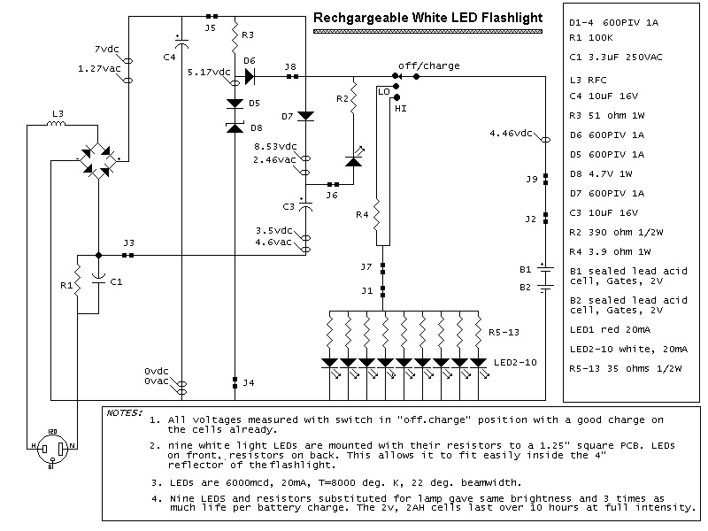
With a flashlight using two small gates sealed lead acid batteries rechargeable (4VDC), the fully charged voltage will be 4.4VDC. Since 3.5VDC corresponds to 20 mA on the graph, the series resistor must drop 0.9VDC at 20mA. A 45 ohm resistor should do the job. At 4V, 25 ohms is more appropriate. I used 35 ohms on each LED in this nine-LED design, as a good compromise.
Note: when the supply voltage is close to the LED voltage, the resistance value is more critical and difficult to select. There are other ways to limit the current, using a PWM or linear curent regulator, and this will be left to the reader to examine. The LM350 linear IC regulator can be configured to limit the current precisely. If you are using such a regulator with several LEDs in parallel, each will have to have a small-value series resistor, to help equalize the current through the array (unless you want to use 9 IC regulators!). Also be aware that a simple regulator like the LM350 has a certain amount of voltage drop across it (about 1.2V) in order to operate.
Here is a schematic of a rechargeable 9-LED flashlight using two Gates SLA cells and nine LEDs. It is as bright as when the single bulb was used, and lasts 3 times longer per charge. That is about 10 hours of bright light, at a lower brightness, is available for about 10 hours more (at the risk of abusing the rechargeable cells). At that point, the regular bulb would have long ago gone dark. LED flashlights continue to produce usable light for so long because the resistance of the LED increases sharply as the voltage decreases below a certain point, yet the LED continues to produce light. At the time that flashlight was built in 2002, the brightest LEDs reasonably available were rated at 6000mCd. Things are only getting better.
The next design in the works will use an array of 36 LEDs, mounted on a 2" diameter circuit board salvaged from an IR illuminator which was part of a security system. This will be placed inside the 5" reflector of a larger flashlight of the type which uses a 6 volt "lantern battery". The reason that a much larger reflector is needed, is because the resistors stick out the back of the improvised PCB, and it all has to fit inside the cone-shaped area of the reflector. The reflector is not really needed, since almost all the light fires straight out the fronts of the LEDs. With 6VDC, 125 ohms is a good resistance for each LED. When the battery is new, and putting out about 6.4VDC, current will be 24 mA, within acceptable limits. This would be a very good place to put an LM350 current regulator in series with the array, and a 47 ohm resistor in series with each LED to equalize the current. This array will consume 700-800mA just like the original incandensant bulb. I am looking for brightness here, not battery life, althought I am considering an extra switch so I can select a few (7 or 9?) LEDs in the center of the array when I want less light and longer battery life. If you use an LM350, the current limiting resistance can be changed to adjust the light output as well.
Some companies make LED driver ICs which use a switched capacitor topology to deliver a precise current to an LED. Most of these, however, are small surface mount parts, and can control only 4 LEDs. They find application in cellphones and other small electronics devices and are very efficient.
One thing to observe when making an array of LEDs is alignment. They all need to point exactly the same way if you want a tight beam. LEDs often have little 'bumps' on the heads next to the LED body base. This makes it a bit tough to fit them flat to a circuit board. Small standoff/spacers made for the purpose can be bought or made. The LEDS I got from LEDTRONICS don't have these 'bumps' and fit nicly to the PCB.
As always, this information is provided without warranty of any kind, and you assume all responsibility and liability.
Happy experimenting!