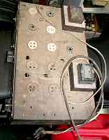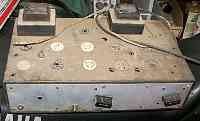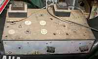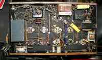


The principle is simple. The cathode modulator's series-pass tubes are in series with the cathode of the modulated stage, so that the amount of grid bias on the series tubes determines the amount of current flowing through them. The current through the pass tubes will have a definite maximum level depending on the current carrying capacity of them and also the amount of curent the RF amplifier can draw. If the pass-tube current is set to about 1/2 of maximum, then the carrier level will be about right for AM. The average DC plate voltage on the RF amplifier never changes. A small, low voltage / high current tube arrangement like this could control a much larger RF amplifier. Although it has to pass the full current required by the RF stage, it only has to withstand enough voltage to completely cut off the stage against the RF drive on the RF stage grid.

|

|

|

|