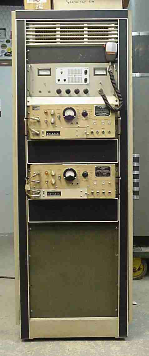
 The rack complete and ready for use. Yes, this is one of the things I do for fun when it's too hot to play outside. I put gear in racks and get them ready. Think of it as part of a grownup set of tinkertoys or erector set, where one has built a subassembly for integration into the whole. sick, eh? |
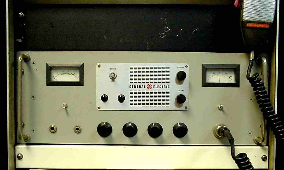 GE MASTR II VHF FM tranceiver using crystals for 146.700MHz wideband FM at 50 watts. The rackmount chassis is handmade. Some OM took alot of time and effort to build this so nicely, so the least we can do is preserve and operate it. |
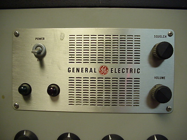 MASTR II front panel. This entire rackmount unit actually has three rackmounted chasis' inside, mounted front-to-back (sorry no pics right now). The power supply, transmitter, and receiver are all separate. vacuum tubes are used throughout except in the power supply where diodes are used. Normally, these commercial units would be mounted inside a commercial-type commo rack and the meters and controls would not be present for the non-technical operator to fiddle with, except for the simple control panel shown with the power switch, speaker, volume, microphone, and squelch. |
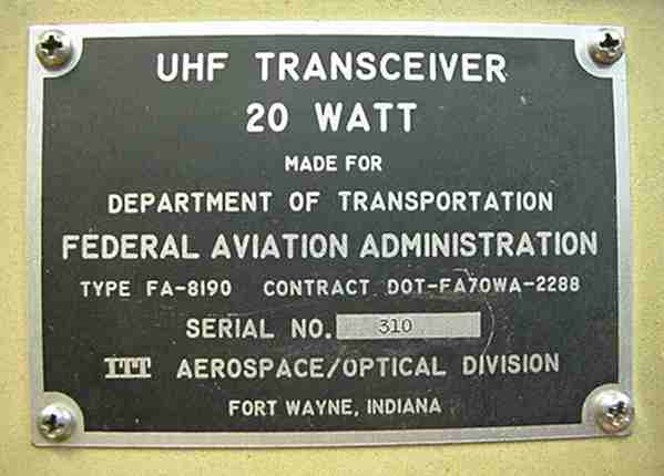
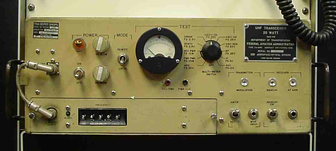 FA-8190 UHF AM Tranceiver covers 230 to 399.5 Mhz with 20 watts output. The 80-lb unit is early solid state with frequency synthesis. This is normally used for communicating with military aircraft. It is fully functional, but its current role will be limited to monitoring the emergency frequency of 243 MHz. |
 |
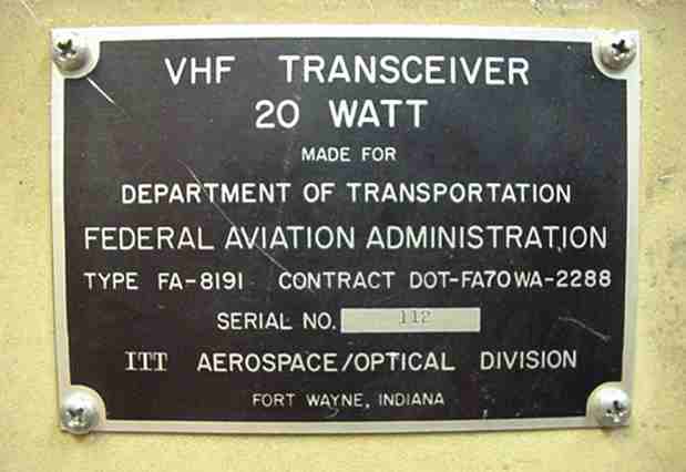
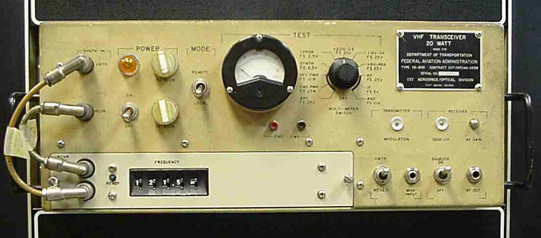 FA-8191 VHF AM Tranceiver covers 118 to 135.975 Mhz with 20 watts output. The 80-lb unit is early solid state with frequency synthesis. This is normally used for communicating with civillian aircraft. It is fully functional, but its current role will be limited to monitoring the emergency frequency of 121.5 MHz. |
|
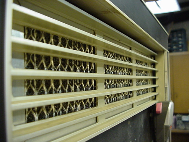 Top-Feed cooling system. Ever get tired of your equipment racks sucking up all the dust and dirt off the floor and blowing it into your costly radio gear? If you do it correctly, you can draw clean air in at the top, and let it exit at the bottom of the rack. Notice that the filters are still employed although not as necessary as before. Digital Equipment Corporation did this cooling scheme very successfully with some of their older machines which were designed to sit on an office floor. Such machines are generally quite clean inside after 15 years, when you find them. Another advantage of top-feed cooling is these stylish blower intake grilles. Why hide them at the bottom rear of the rack? |
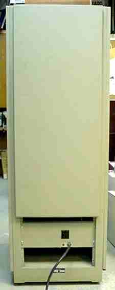 The air exits at the bottom rear of the rack, carrying away the heat of the equipment. It is important to make sure the rack is fairly air-tight (as racks go) so that the air must pass through the rack to the exit and take away the heat. The capacity of the blower is important. Use at least 200CFM for every 400 watts of dissipation. Fans are not as satisfactory because they do not generate much pressure. Higher pressure from a squirrel-cage blower assures the air will move against natural convection. The blower must be placed at the top, so that the rack fills with cool air from the top down. Any hot air convected from equipment not directly in the air flow mixes with the turbulent air and eventually exits at the bottom. To test this concept, a 500W heater was placed in the rack with the blower running. The rack stayed cool inside, and the exit air was only slightly warm. |