Testing AM / High-Level Plate Modulators Independent of the Transmitter
Some tips for safety and useful methods.
Home
Many times, the experimenter has found a set of hardware for a modulator, or even a complete modulation deck and would like to know if it might be useful in conjunction with a known transmitter's PA stage. Less frequently, the modulator is already present, but the RF stage has yet to be built.
The first thing that must be done is to determine the optimum load resistance and the maximum undistorted power output of the modulator. Where any sort of "high voltage" is to be used, this process can be risky and if any mistake is made, it could prove deadly, or at least cause damage to some expensive equipment or destruction of hard to find components. I won't harp on it. If you don't understand, find a friend who does, otherwise it's like playing with nitroglycerin and no one wants an accident, that would just suck all the fun right out of it.

Here I will show some techniques and options, as well as supply an excel workbook that will show what the modulator can do under different circumstances of load impedance that will be presented by as many RF amplifiers. Several results from different loads can be entered side by side for comparison. I put the workbook together due to my own need to check out the modulator in the old Colonel.
First, you need some basic means to work with the high voltages and the heat from any load resistors. You may have to "work the rig hot", meaning having the rig on in standby, and turning the high voltage ON during the tests and OFF between them when you change things around. The examples for this hazard are from an old home-brewed HF transmitter (The "COL. Tucker") using a pair of 3-500Z triodes for the modulator and a 4-1000 for the RF stage, running at about 3000 volts from two separate power supplies, one for the modulator and one for the RF PA, each of which can deliver almost 1 Ampere continuously. This transmitter is very dangerous when opened up and makes a good and frightening example. But just because you are fiddling with one that makes only 400 volts, don't feel too safe, it is ready to kill too.
Since a modulator is simply a large audio amplifier, testing it will require a load resistance. Never turn on a modulator with no load. The transformer can be destroyed by excess voltage. Some experimenters will demand a non-inductive resistance, but it is not really necesary because the frequency range of interest will seldom extend above 10 KC, and more likely the actual operation, once connected to a transmitter, will have almost no meaningful content above 3.5KC.
Provision must be made to remove the RF PA stage high voltage plate supply from the secondary of the modulation transformer. The other end of the secondary, normally connected to the RF PA B+ input, must also be disconnected. This article assumes no RF screen or driver modulation winding is present. If they are present, these can be disconnected and ignored because the vast majority of the power is provided by the plate modulation winding.
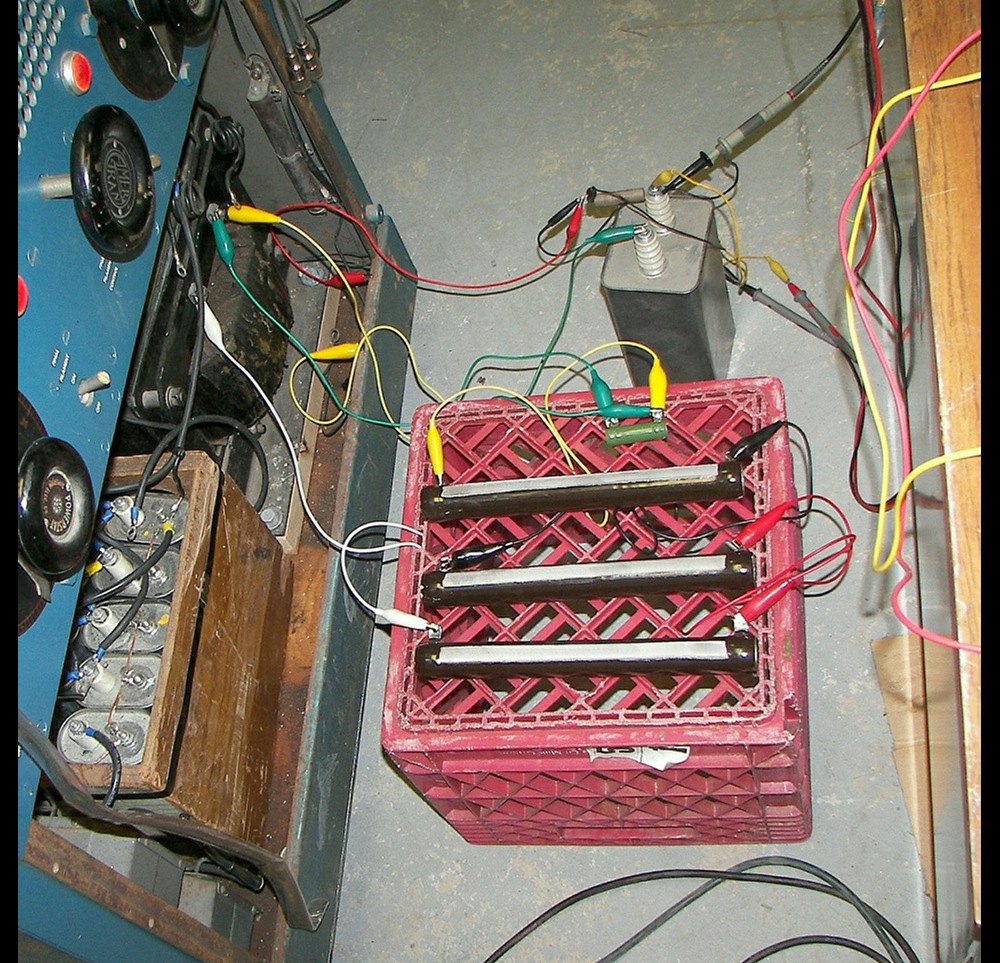
The image shows one way of arranging things so there is little chance of an arc or short. Load resistors sit on an insulating platform and are connected to modulation transformer secondary with clip leads. The platform is plastic and could melt a little. Putting a piece of glass on top would be better. Don't set the parts on concrete, as it is not a good insulator. Note the leads, except for the ground leads, are arranged so they do not lie on or near the chassis nor on anything esle conductive. The slack was taken up in some of the leads by tucking it into holes in the insulating platform. The 3000V supply and RF amp have been disconnected from the transformer secondary. A small resistor used for pick-off voltage is connected to a well-insulated oil cap a few inches from the load. At the oil cap, a discharge resistor, ground, RMS AC voltmeter, and scope lead are attached. As mentioned, one end of the secondary is grounded.
If the transformer on hand might not take a situatiuon where the primary has full voltage and the secondary has one end at ground, then it is safe and possible, with the circuit shown below, to run the tests with the B+ connected to the transformer secondary, and the RF PA connection removed only. The drawback of this is that any hum and noise on the B+ line will show up in the signal. The experimenter can decide, and can mentally remove any power suply artifacts from the measurements.
The image shows the hookup to the output of the modulator. The bulk resistor serves as the load resistance and dissipates nearly all of the power. The tap resistor near the ground/cold end of the circuit picks off a small sample of the secondary voltage (in this exaple the secondary can make about 6000 volts peak to peak). The lower voltage (<100V) from the tap resistor is passed through a 1uF 15KV capacitor. This is a safety measure. Should something happen and the B+ appear on the modulation transformer secondary, the capacitor will attempt to prevent a catastrophy. The 10K resistor from the capacitor's output to GND serves to allow the capacitor to charge and discharge. It should not have to be mentioned that the capcitor must always be discharged properly for safety reasons when changing resistances, etc.
The experimenter will usually look in the tube manuals and have some idea of the RF stage operating DC voltage and current they would lie to run in the modulated stage.The load resistance to start experimenting with can be roughly calculated by dividing the desired RF stage's DC voltage by its amperes. E/I=R, therefore a stage running at 3000V and 0.4A would present a load of 7500 Ohms. It does no harm to make this assumption now, because the voltage to current ratio of the RF stage can be altered slightly by the experimenter to make the most use of an available modulator.
It would also be good to mention the well known fact that the modulator has to be able to supply a RMS wattage equal to at least half the RF stage's DC input. With a given modulator that will not quite make enough power, the RF stage's DC input under carrier conditions can be reduced to permit 100% modulation.
Many builders choose to use a modulator capable of as much RMS output as the RF stage DC input. One reason for this is so that the modulator is never over-taxed and is unlikely to clip during normal operation. Another reason for this practice is so that a slight impedance mismatch between the modulator and RF stage is tolerable while still acheiving 100% modulation.
It is also important when testing a modulator to have a driver with more than enough power and a low output impedance. A good rule is to use a driver with at least twice the required power. This keeps distorion down and also allows better regulation of the drive over the audio half-cycle.
The image shows an example of a beam power tube 40 watt amplifier with a low output impedance and good regulation. This is basically an old 50 watt public address amplifier converted to a hi-fi amplifier. The conversion was possible because the output transformer is of very good quality. The 25V winding on the output transformer was used to buck the cathode current, resulting in -10dB feedback directly in the output stage, giving very good regulation. This is shown because some peope prefer only triodes for drivers, but a good driver can be done with almost any tube.
Notice that in this case, it is necessary to match the amplifier's output winding of 16 ohms to the 500 Ohm input of the modulator. This was done by using a spare output transformer that had taps for 0-4-8-16-125-250-500 Ohms. Normally a 500 Ohm line from the speech amplifier to the modulator is balanced about ground. The common (0) output of the amp is grounded, causing one side of the 500 Ohm line to the modulator to also be grounded, but this has not caused any issues while testing the modulator.
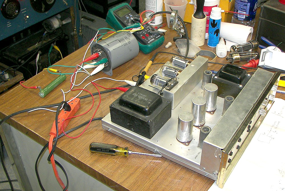
The next image shows the hookup on the workbench of a hi-fi amp and a matching transformer. This amplifier does not have quite enough power to properly drive the modulator in question due to losses in the transformers and other factors. Another amp is being prepared.
For the general setup, regardless of the driver selected, an audio oscillator is used at about 400Hz. The purpose of a test point on the driver amplifier is to make sure it is not clipping before the modulator. When clipping occurs, as shown on the dual-channel scope, the driver amp should be clean, and the modulator should be the first to distort or clip. More advanced experimenters will want to use a function generator to sweep the audio frequency and determine the flatness of the modulator regarding frequency response. -But the testing means nothing if the driver is not flat, well-regulated, and clean.
The image shows a 200 watt amplifier with a 500 Ohm output. This is ideal for testing a large modulator. Care must be used not to overdrive the modulator's grids.
The spreadsheet is the real tool here. with a handful of 1000-2500 Ohm 200 watt resistors, many impedances can be tried on the modulator, and the optimum load found. If the modulator is found to provide more power than required for the (DC input) conditions of the RF amplifier, all the better. Let it coast along and faithfully reproduce your speech.
Although these tips are intended for those with a modulator that is divorced from the speech amp or driver, they can be used to determine modulator load and power with any analog modulator, even solid state ones, as long as the voltages and currents are scaled appropriately.
There is no theoretical difference between a pair of 807's, transformer-driven in class AB2 by a 6AQ5, and the larger modulator described here, except in that case the driver is probably built on the same chassis for a small 80-120 watt modulator like that, and therefore the driver test point would be the anode of the 6AQ5. Smaller modulators will nearly always have the driver right there. Makes it real simple!
I'd also like to mention an often-overlooked source of impedance matching transformers - the "70V line transformer" (in Europe, 100V is the common standard). They come in various wattages and impedance ratios and could be useful for driving certain tubes from 4-16 Ohm outputs of common amplifiers.
The usual calculations will reveal the turns ratios and impedance ratios. The 'real' example on the right shows that if the primary were driven with a voltage equivalent to 32 watts to the appropriate impedance tap on the impedance side, the entire voltage side would provide 140V RMS (198V peak), with the 32W tap being the center tap.
That is to say, 11.6 volts RMS applied between the "0" and "4" Ohm taps would yield 70V RMS between taps "C" and "32W" and 70V RMS (99V pk) between taps "32W" and "8W". This could drive a pair of 3-500Z's (peak grid voltage + and - 99V) with decent voice quality asuming the transformer is made well. So don't overlook them. They are inexpensive and easy to buy.
Next steps: Once the best load for the modulator has been found, and it has been determined that the existing RF stage can operate with that condition, it's time to do some work on the modulator to reduce distortion. I won't go into that in detail because there are already many examples.
Overall feedback from the modulator plates via a string of resistors is one way this was done with older broadcast transmitters. This method is an advantage because it made up for what we might call, without intending any insult, "lack of technology". A 250-watt (carrier) AM BC transmitter from 1947, such as the RCA BTA-250L, would typically have a frequency response of 30 to 10,000 cycles +/-1.5dB with less than 3% distortion. That was better than most people's home hi-fi gear of the day. Check the link for the manual, and have a look at the modulation system. It's class AB1, uses beam tetrodes, and the performance is great!
If this has been of interest, please visit AMFONE.net for more information on technical AM topics with a focus on amateur radio.