
|
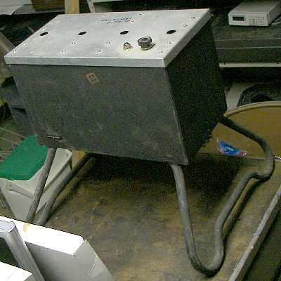
The BC-902 transmitter is a plate-modulated AM unit with selectable tones of 400, 1300, and 3000Hz, as well as tone cycle repetition rates of 2 and 6 Hz. The combination of these functions is selected by a three position rotary switch on the front (top) panel.
The selection is made according to what function in the ILS system the transmitter will play. A discussion of the workings of a modern ILS system is beyond the scope of the discussion of this transmitter, but it is worthwhile to say that the BC-902 transmitter and antenna, referred to as a marker, is placed a distance out from the runway or airport to let the pilot and the onboard avionics know that the approach is near. Fear not, even though the frequency and signal types have remained unchanged for decades and one -could- theoretically substitute an BC-902 in a pinch, modern gear is always used today! The text on wikipedia.org explains the typical use of three markers (see ILS) in laymans' terms:
The outer marker should be located 7.2 km (3.9 NM) from the threshold except that, where this distance is not practicable, the outer marker may be located between 6.5 and 11.1 km (3.5 and 6 NM) from the threshold. The modulation is repeated Morse-style dashes of a 400 Hz tone. The cockpit indicator is a blue lamp that flashes in unison with the received audio code. The purpose of this beacon is to provide height, distance and equipment functioning checks to aircraft on intermediate and final approach.
The middle marker should be located so as to indicate, in low visibility conditions, the missed approach point, and the point that visual contact with the runway is imminent, Ideally at a distance of approximately 3,500 ft (1,100 m) from the threshold. It is modulated with a 1300 Hz tone as alternating dots and dashes. The cockpit indicator is an amber lamp that flashes in unison with the received audio code.
The inner marker, when installed, shall be located so as to indicate in low visibility conditions the imminence of arrival at the runway threshold. This is typically the position of an aircraft at a distance of approximately 100 ft (30 m) from the threshold. The modulation is Morse-style dots at 3000 Hz. The cockpit indicator is a white lamp that flashes in unison with the received audio code.
The specimen pictured is missing the antenna feedthrough insulators. They should be sticking up from the center holes. It is not known what goes in the outer holes. There is a headphone jack underneath for monitoring the audio signal being transmitted. The nameplate is missing but it should be on the top near the viewer, where the pattern of four small screws is located.
date: 1942
Page 1 of 10