Installing Aux. 24V and 12V Power and an AN/VIC-4 Intercom in an M35 Military Truck
These targets link to medium sized pictures. Click here for larger images.
In order to provide a reliable 14V/12V system, a battery equalizer such as the kind used on motor coaches was installed. It was found that the equalizer, in an effort to always maintain the 'lower' battery at precisely 1/2 the voltage of the the total series arrangement of the two batteries, would slowly discharge the upper battery over a period of about a month or two. The lower battery was always found to be fully charged.
In a motor coach or bus, which runs every day, this behavior is not an issue. To improve the behavior, a heavy duty 2-pole normally open contactor was installed between the 12V and 24V points in the battery system and the 12V and 24V points on the equalizer. When the main power to the truck is 'off', the contactor is not energized and the battery equalizer is disconnected. The equalizer used is a 50-amp unit, meaning that it can supply up to 50 amps to a 12V load and draw this power from the truck's 24V system. This way, the 12V load current is not drawn through the upper battery resulting in an overcharge condition, nor is the 12V load supplied exclusively by the lower battery which would result in a discharge condition. With small loads lie a CB radio, this is not very important except to purists, but when a serious load is to be used, such as a 100 watt ham radio set, the requirement for some kind of solution like this is very real.
The additional feature of using a contactor allows the 12V and 24V auxiliary power to be switched on and off, a great convenience. I chose to take my contactor coil energizing voltage right from the DC input to the manifold heater switch. This is a convenient point, and is switched by the main power switch of the truck. Others may wish to install a separate toggle switch to operate the system independently but to me that is a hassle and I wanted to avoid the possibility of leaving aux. power 'on' by mistake.
Obviously, wiring has to be run to do something like this. The contactor is on the back wall of the cab and the switched 24V power is behind the dashboard. The M35 has no carpet to 'hide' wiring under, and I didn't want to commit to a conduit along the floor from under the seat to the firewall. There's no real obvious way to run wire from behind the seat to the inside of the dash. If I was going to do this, I wanted to run several wires to the dash, so I would not have to do it again later. 3/4" split plastic wire loom was used, and with some effort, I slipped three 12-guage, one 16 guage, and one CAT-5 cable into it. The 16-guage is for the contactor coil power, the 12-guage wires are for 12 or 24V operated accessories requiring switched power, and the CAT-5 was for the heck of it. Why not? if not used for its usual purpose, it's great for extension speakers and low-level controls which any electronics hobbyist might think of using.
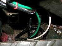
The cable assembly is 22 feet long, with a loom length of 20 FT. and 1 FT of wiring sticking out of each end. There neded up being about 2 FT extra length, so it was just right. This extra length was coiled up inderneath the chassis and attached to the crossmember that goes between the transmission and transfer cases. Having the excess in that space allows the possibility to loosen it up in order to remove various vehcile components like the master cylinder and air servo and whatever else might need to be serviced at some future time. The routing of the cable goes generally from the middle of the dash, above the steerring column, and up and out through the rubber grommet of the hot water cab heater wiring (hole enlarged) and then doen along the wiring harness past the flasher and past the throttle linkage, to the frame rail space just forward of the brake system. The cable is wire-tied to various air lines and wiring harness along the way. Once it is crossed over to the other side of the frame, it passes over the frame rail to the space behind the battery box, and then bac to the rear of the cab floor and from there up into the cab behind the passenger seat. I had already drilled a 1.5" hole in the floor of the cab behind the passenger seat to accommodate the 6-guage wiring to the battery equalizer. It took only about 20 minutes to run the cable, once I decided to just get dirty and do it.
Now that switched power is available, the VIC-4 intercom can be operated more conveniently. It does have its own power switch but if I forget, it won't run the batteries down when the truck is off. --More Later!
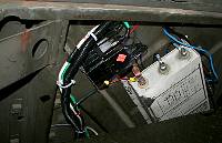
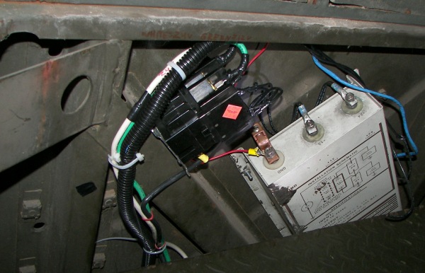
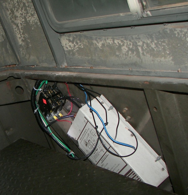
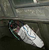
The large white box is the battery equalizer. It's actually a glorified 24V to 12V switching converter that maintains Vout=Vin/2 within a couple percent at up to 50 amps.
|
The black contactor is a potter and Brumfield P30 series DPST NO 30A unit. It's resistive load rating is 40A/600VAC, so there should be no concern about overloads, even at the occasional 50A surge. It was what was on hand, and they are not inexpensive so the choice was made. Whatever contactor you choose, make sure the coil is rated for continuous duty (unlike a starter solenoid for instance which is for intermittent duty only).
|
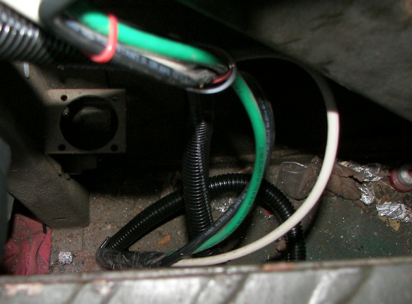
The heavy wires from the batteries as well as the new cable pass throught he cab floor behind the passenger seat.
|
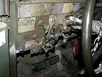
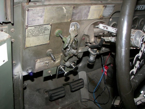
While I was at it, the blue indicator lamp I chose for the manifold flame heater detection kit was installed. Note the two-tone paint job on the security chain.
|
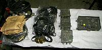
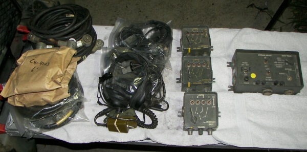
AN/VIC-4 system with three stations.
|
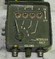
amplifier audio frequency, p/n 12310227, nsn 5895-01-144-5790
|
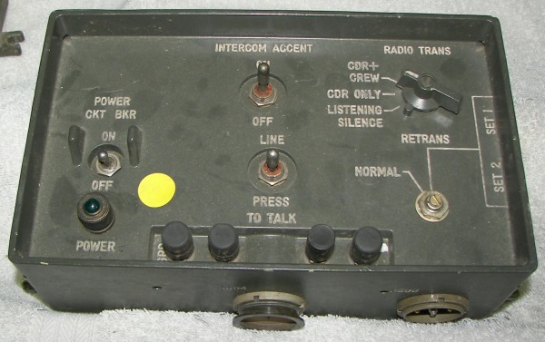
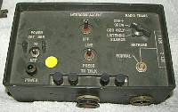
control, intercommunication unit, model m981, p/n 12310226, nsn 5895-01-144-5995
|
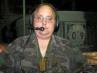
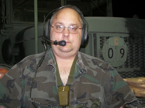
H-161/GR headset
|
larger images
schematic wiring diagram
Next Page
Page 1 of 4