Shalcross 673-D Milliohmmeter Schematic Wiring Diagram
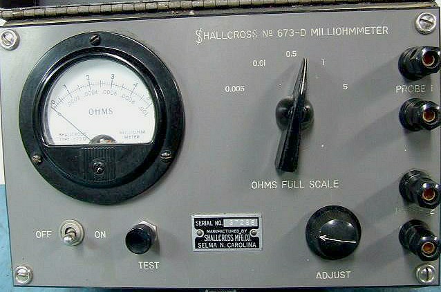
As-found, it needs the power switch replaced and the meter's scale is partially in contact with the needle at the top of the scale, so it might have been dropped. Otherwise, the meter seems fine and the instrument seems undamaged. The scale can be bent back carefully once the meter movement is disassembled.
There are no component values on the schematic because the meter movement will interfere with any resistance measurements and the resistors are not marked, being custom made.
Some testing was done, and it seems to measure low resistances all right, but either I do not know how to operate it or there is something screwy with the operation when the power is turned on.
When the power is turned on, one would expect to set the Ohms, then push the button to check the unknown resistance. Nothing happens when the power is turned on. I am probably not doing it right with regard to the probes.
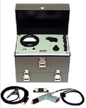
This brings up another interesting feature of this meter. Each probe has two wires. One is for the current path and one is for the voltage reading. That way, the voltage drop in the probe wiring is eliminated. That's important in any meter that reads very low resistances. One proble is a clamp type and one is a pistol grip type with pointy spring-loaded steel tips.
For now, here is the schematic diagram and a brochure. The images are from similar units. The one I have has the dark gray panel instead of the light panel.
Shalcross 673-D Milliohmmeter Schematic Wiring Diagram
Shalcross 673-D Milliohmmeter brochure
If you need such an instrument, you can probably get a like-new calibrated one with the special probes from Tucker Electronics. Otherwise, try your luck here and there. Aside from physical damage throughout the years, there does not seem to be much to go wrong, as long as an incompetent person hasn't worked on it! Be sure to ask for the associated calibrated resistor, the No. 271 test standard. This is a special 0.0025 Ohm 2% resistor specially designed and mounted for checking your Shallcross meter.
As for me, I'll fix my own and make my own probes. That won't be perfect but it will find those bad/burnt connections around the lab and help check some of those 0.05 to 1 Ohm 200W wirewound resistors that always seem to be lying around. I do not know what wire size the factory probes use. If you need to make your own probes, use the most flexible wire possible and at the same time, use the largest guage for the current circuit, at least #10. One decent compromise might be RG-58 or similarly flexible shielded cable. The outer conductor can handle alot of current and the smaller inner conductor is fine for the voltage circuit.
Finally, I don't have a picture of mine yet, but here are a couple images from the internet, just to show what the instrument looks like. I think that's fair enough.
If you have a manual for this, I would be grateful to pay a few bucks for your trouble scanning or copying legibly the instructions, schematic, and parts list, so I'll have something to work with as I progress to the repairs later. Please contact me here:
 .
.
Tucker Electronics
Note it is pristine with the probes and the No. 271 standard
eBay
This one went for > $100 as-is.