North Texas Teslathon 2010
Shocking Images and Videos
Home

four 13.5uF/40KV caps
|

shrinking chamber
|

trigger housing
|

loaded
|

X-ray PSU
|

X-ray PSU
|

33KJ is too much
|

33KJ
|
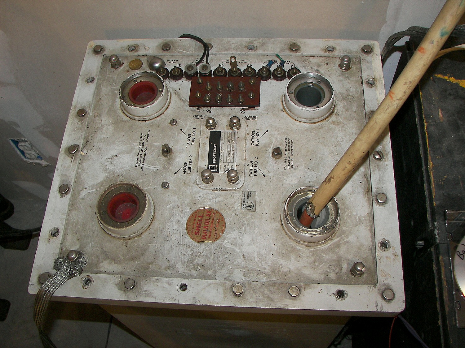
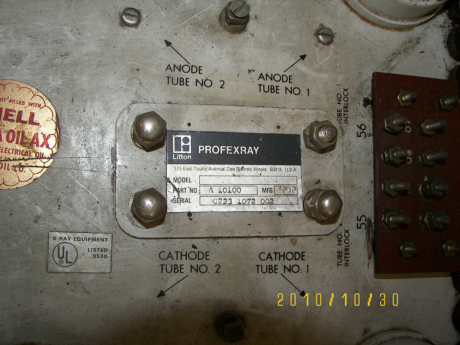
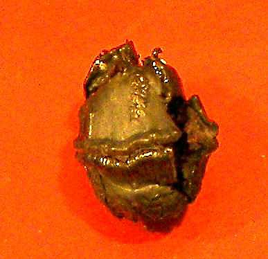
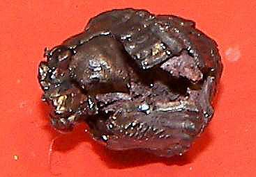
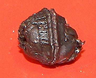
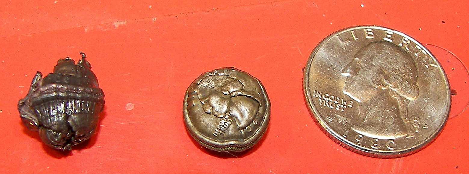
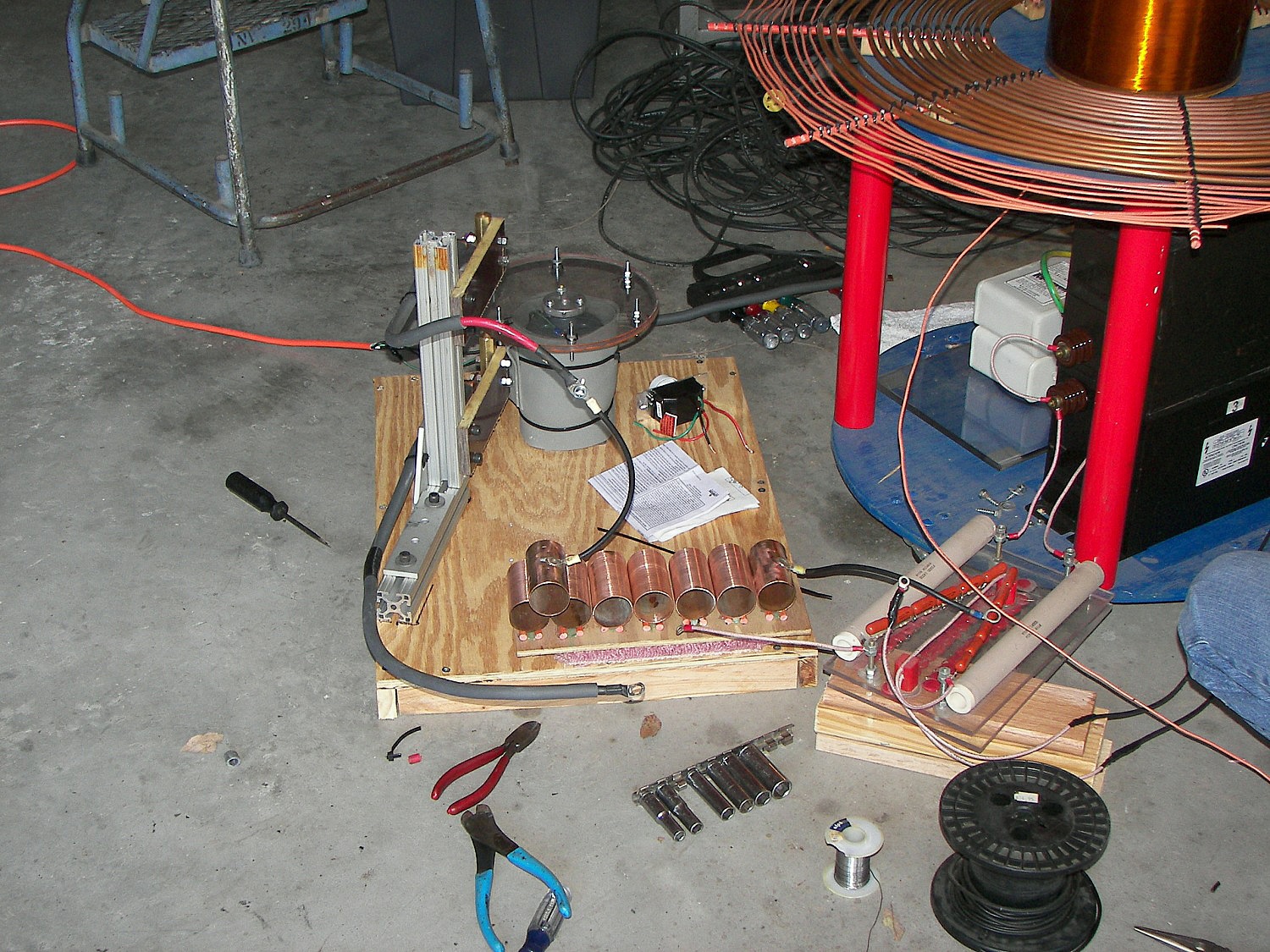
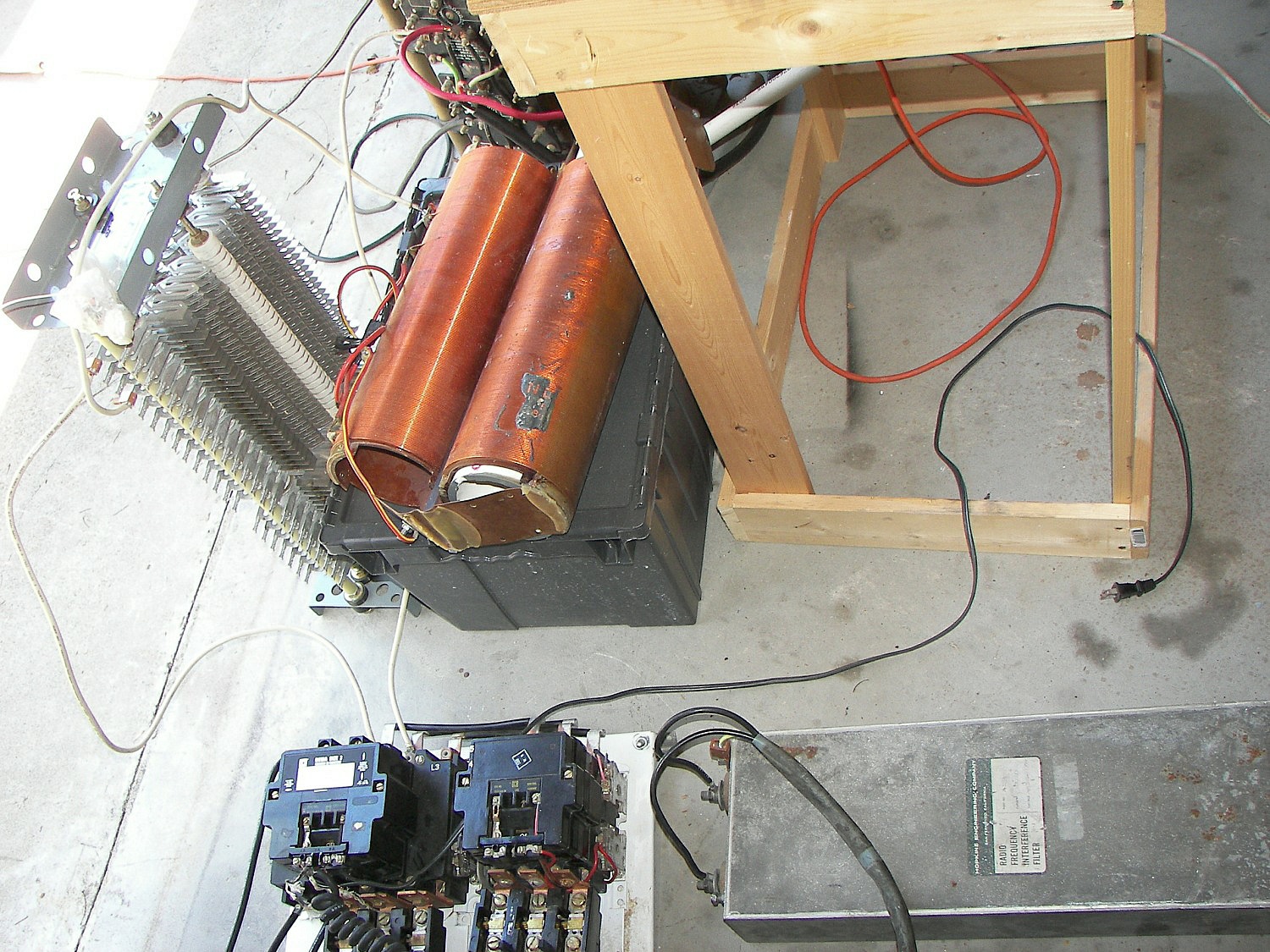
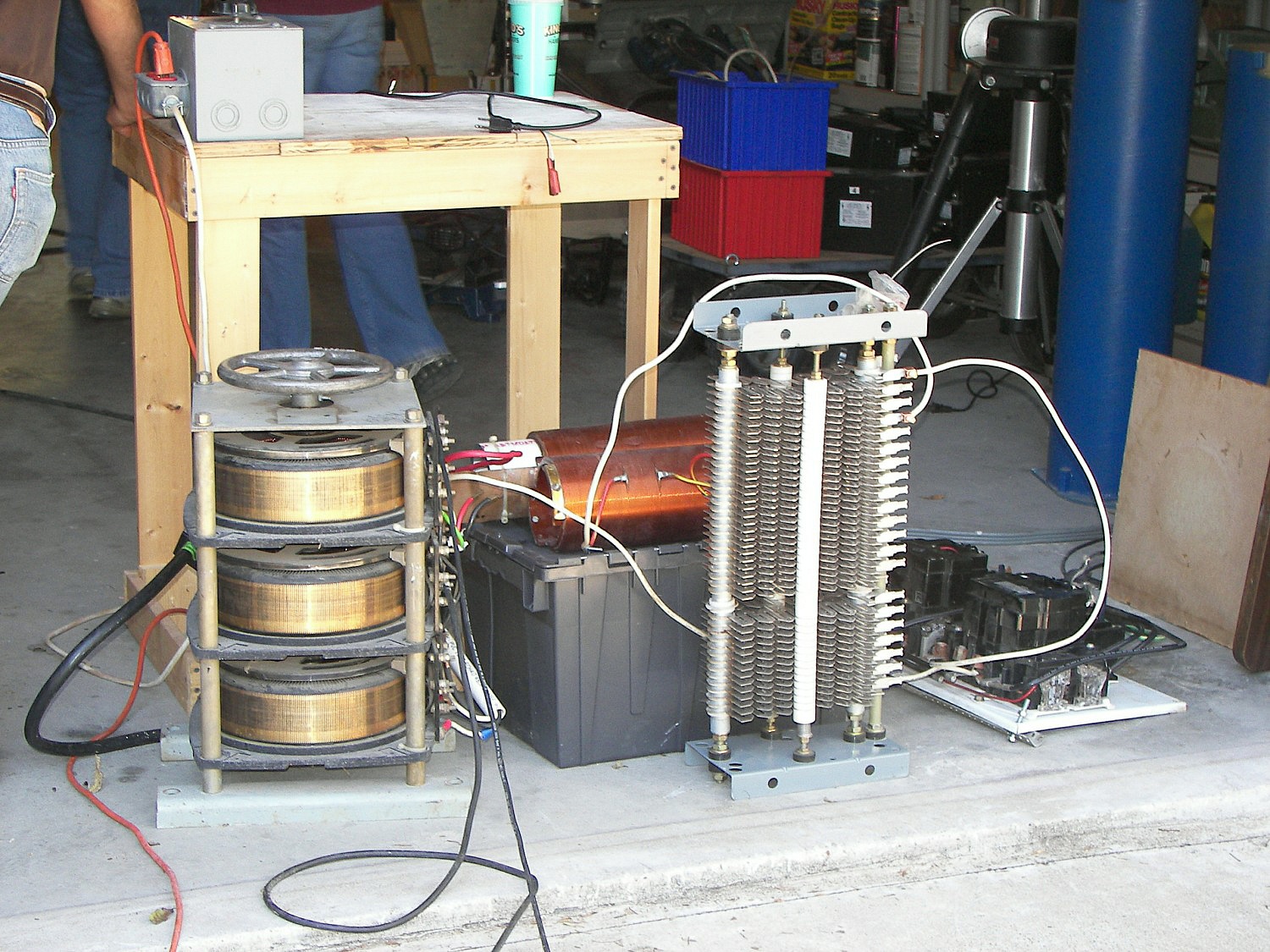
The event began with Wild Bill shrinking some coins. Quarters seemed to be the best targets. A bank of 13.5uF 40KV energy storage capacitors was used. Some experimentation waas required to get the energy delivery profile aligned. This involved adjusting the final charge on the capacitor bank, the number of turns around the coin, and in some cases removing one capacitor from the bank. The work coil was enclosed in a thick wall steel drum with a removable 1/2" thick top. The coil was sandwiched betweek two halves of a section of wooden dowl and the coil slipped oveer it. The assembly was secured with wire ties which were inevitable destroyed along with the coil. In one case, the dowell/coin assembly was wrapped with some thick tape and then the coil slipped on. Interestingly the tape held against the tremendous pressure during the process. The discharge was triggered by a ball gap with a washer in the center. the washer would receive a high voltage pulse from a spark coil and arc to one of the main gap electrodes. This would ionize the air in the gap and initiate the discharge. The process was carried out with the brisance and acoustic volume of a gunshot. To charge the capacitor bank, an X-ray power supply was employed, the voltage being adjusted by a variable autotransformer. Appropriately, a large two pole knife switch was used to connect and disconnect the mains. Between the bank and the load, a transient filter was connected so that any mis-discharge would not go back into the power supply. During one shot, the capacitors were accidentally charged to 38KV. The quarter was nearly destroyed and started to fragment. Considering the quickness with which this happened, perhaps 1 or 2 miliseconds, the peak power may have been 17-35 megawatts. Inside the shrinking chamber may be seen many small pieces of copper from past coils, The coil is sacrificed each shot. Markings on the inside of the chamber reveal the force with which the coil is destroyed during the process. The copper straps are approximately 3" wide and 1/32" thick. After each shot, the bank must be discharged the rest of the way. It may have several hundred volts remaining. A soda can on a stick was used to short the terminals to the case. There ended up being several holes in the can after a few uses. This sort of science fun continued thoughout the event and no one got bored with it at all considering the many factors which could be changed incrementally for each shot and the resulting closely graded sizes of quarters produced. I regret not having an image of all the quarters, but the few shown should illustrate the point.

33KJ
|

L to R: 33KJ, 16KJ, 25c
|

comparisons
|

TC blown secondary
|

Jacob's PSU
|

Jacob's TC
|

small TC
|

small TC
|
At first it was difficult to trigger the discharge gap with the existing automotive ignition coil. A Tesla coil was tried, with the unfortunate result of blowing the secondary off the form as the bank discharged partially through the TC and partially through the work coil. The ignition coil, having a far higher secondary impedance, did not suffer this indignity. The particular image shows that much of the copper was simply vaporized. Until that moment, I had not been acquainted with the odor of copper dust but I affirm it is not really unpleasant.
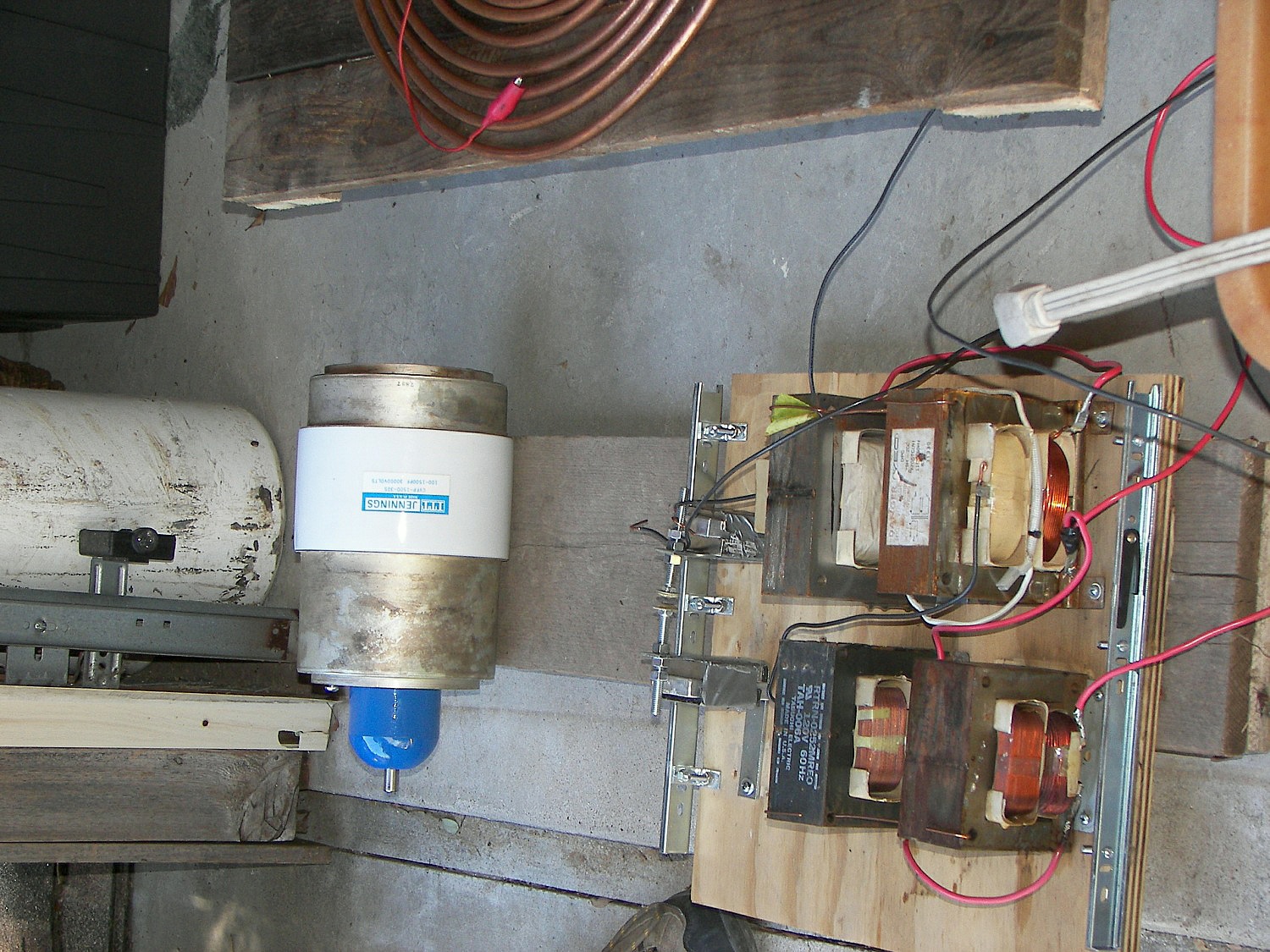
Jacob had built a Tesla coil using four microwave oven transformers for a winding of 4000-0-4000VAC. It was run unballasted with shunts in place. The gap was magnetically quenched as well as blown out by air form a portable drier. One experiment used a Jennings 1500pF vacuum capacitor, but this was not enough. To match the power supply and coil in use, the capacitance would need to be more like 10,000pF and a 60-100mA current limiting device would need to be used on the 500mA PSU for that size coil. The coil also needs more loading on top and the load capacitance should be in the form of a wheel or disc so that the voltage gradient will prevent arcing from the coil winding itself.

small TC
|

small TC
|

small TC
|

small TC
|

small TC
|

small TC
|

small TC
|

small TC
|
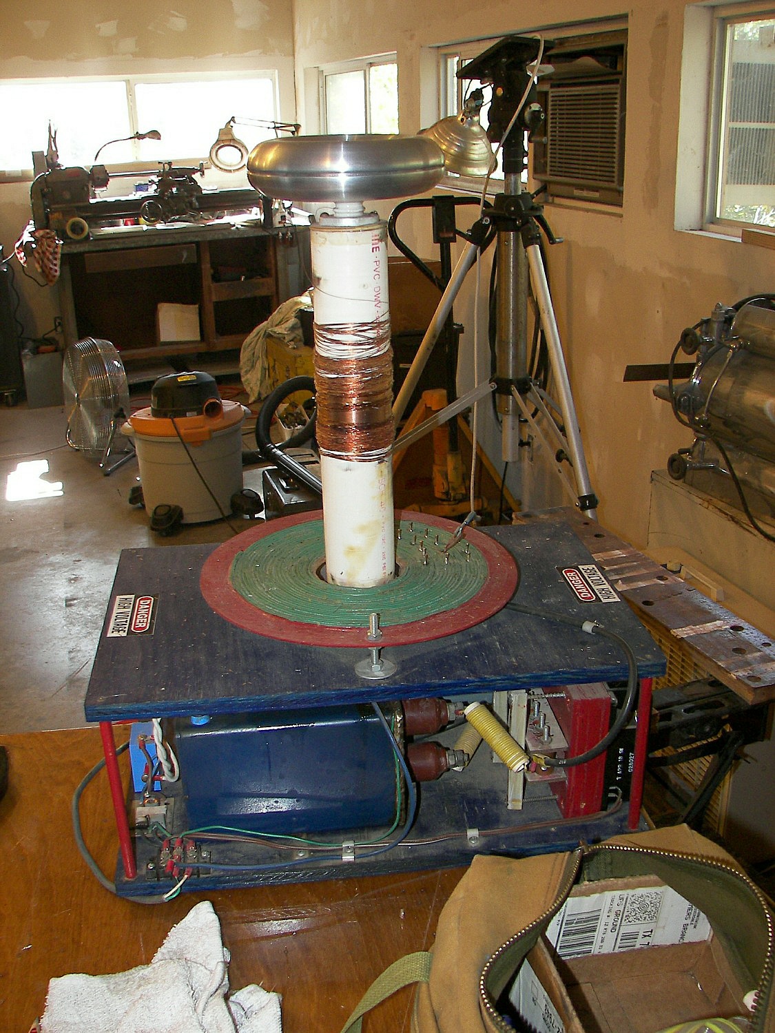
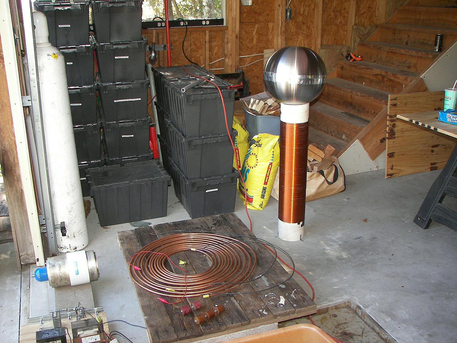
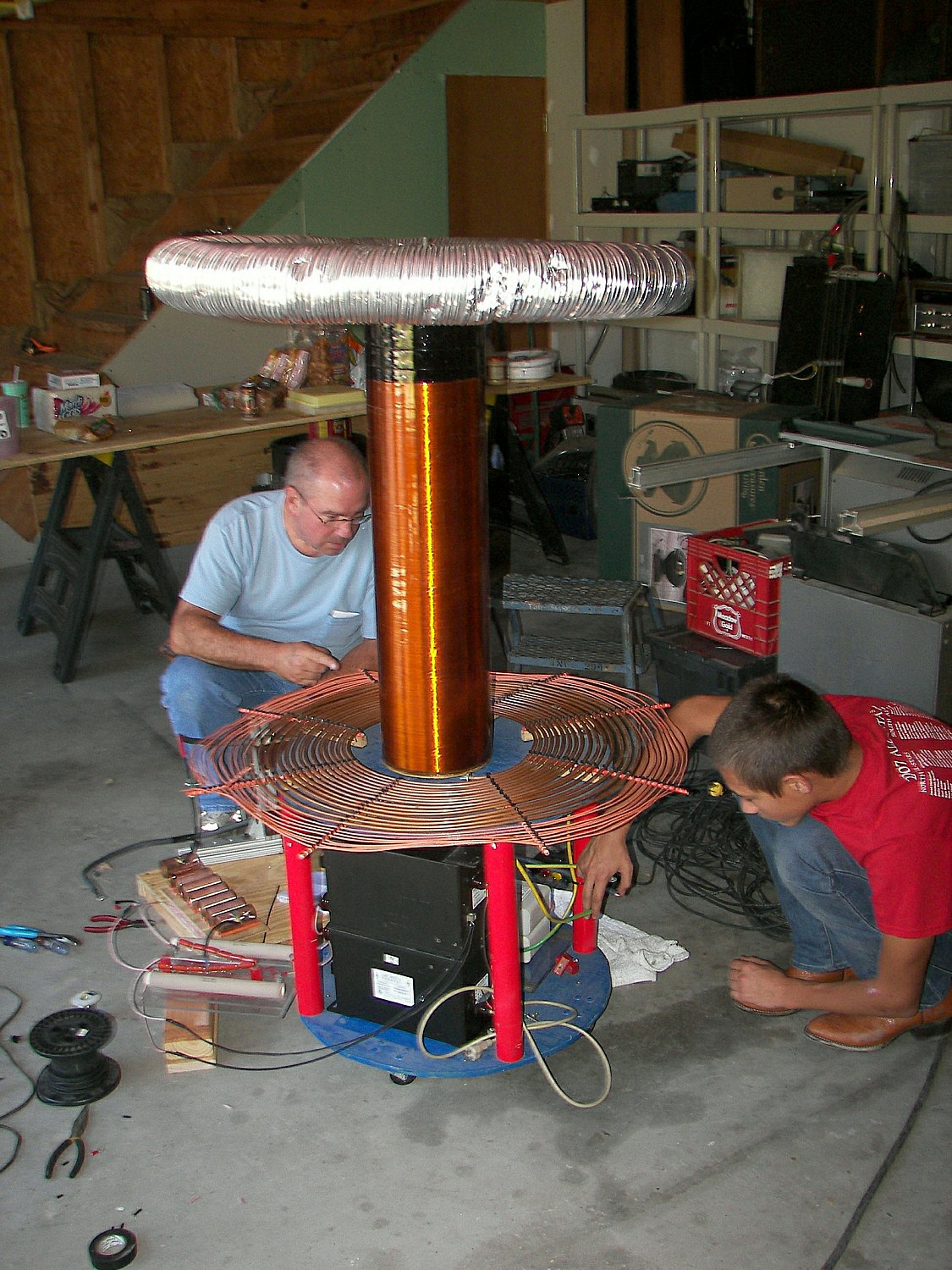
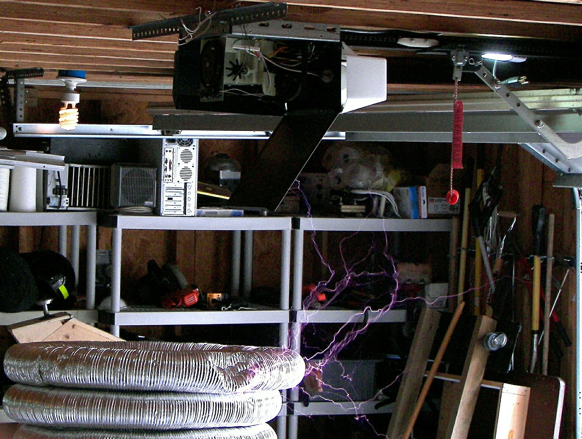
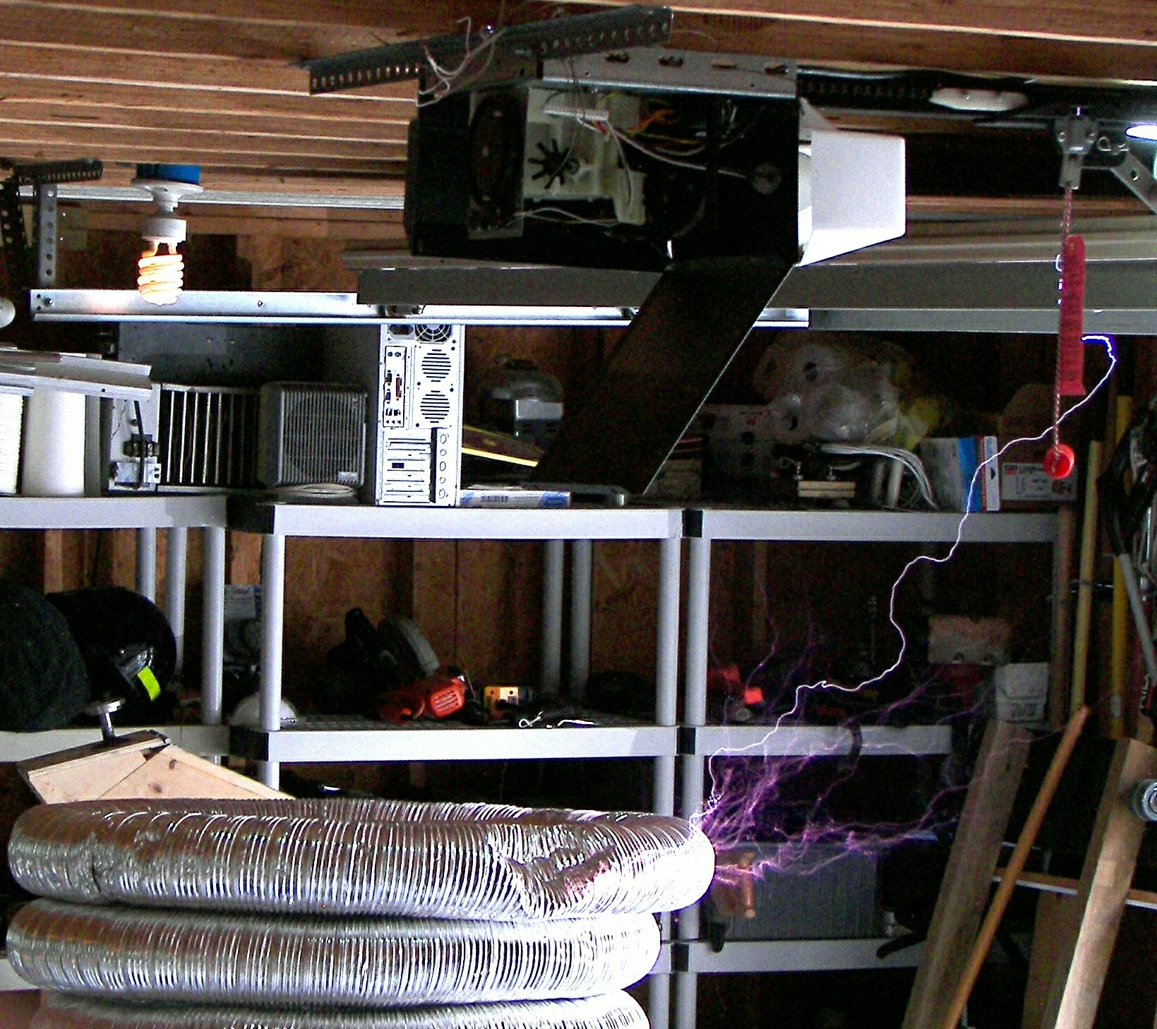
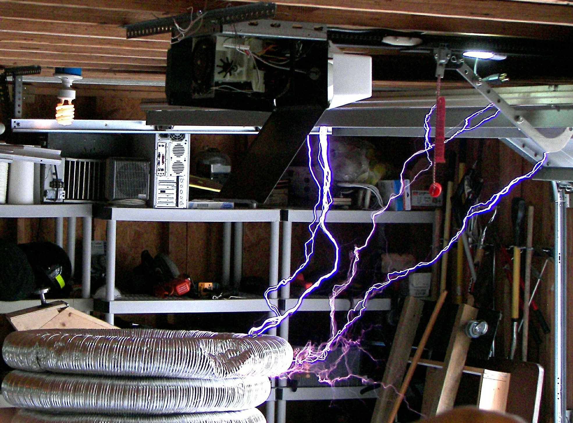
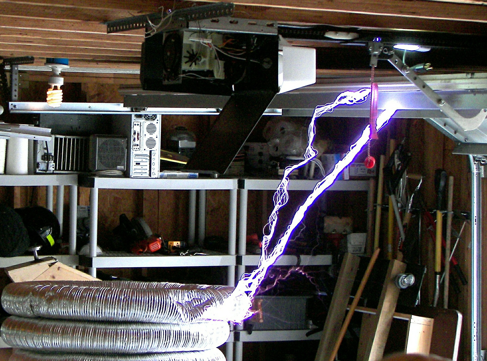
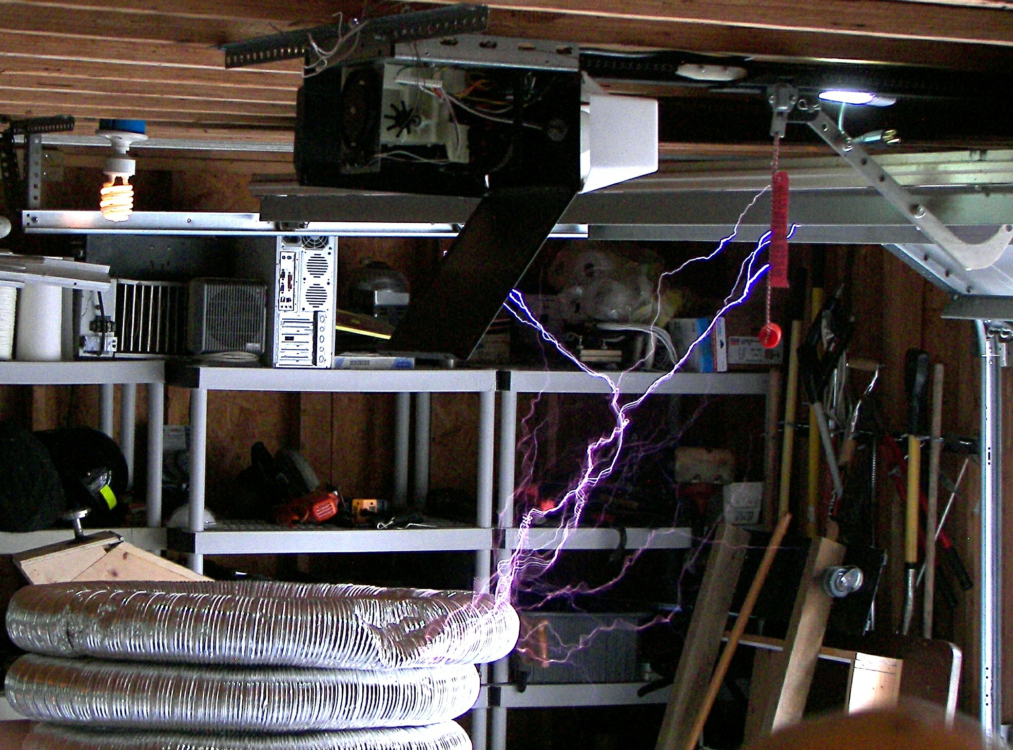
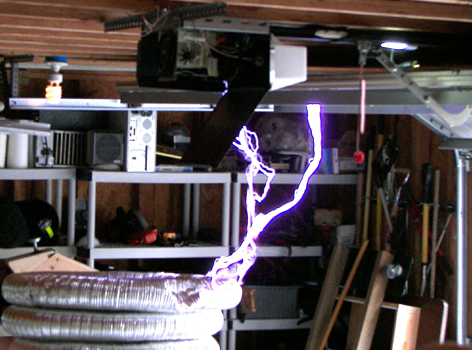
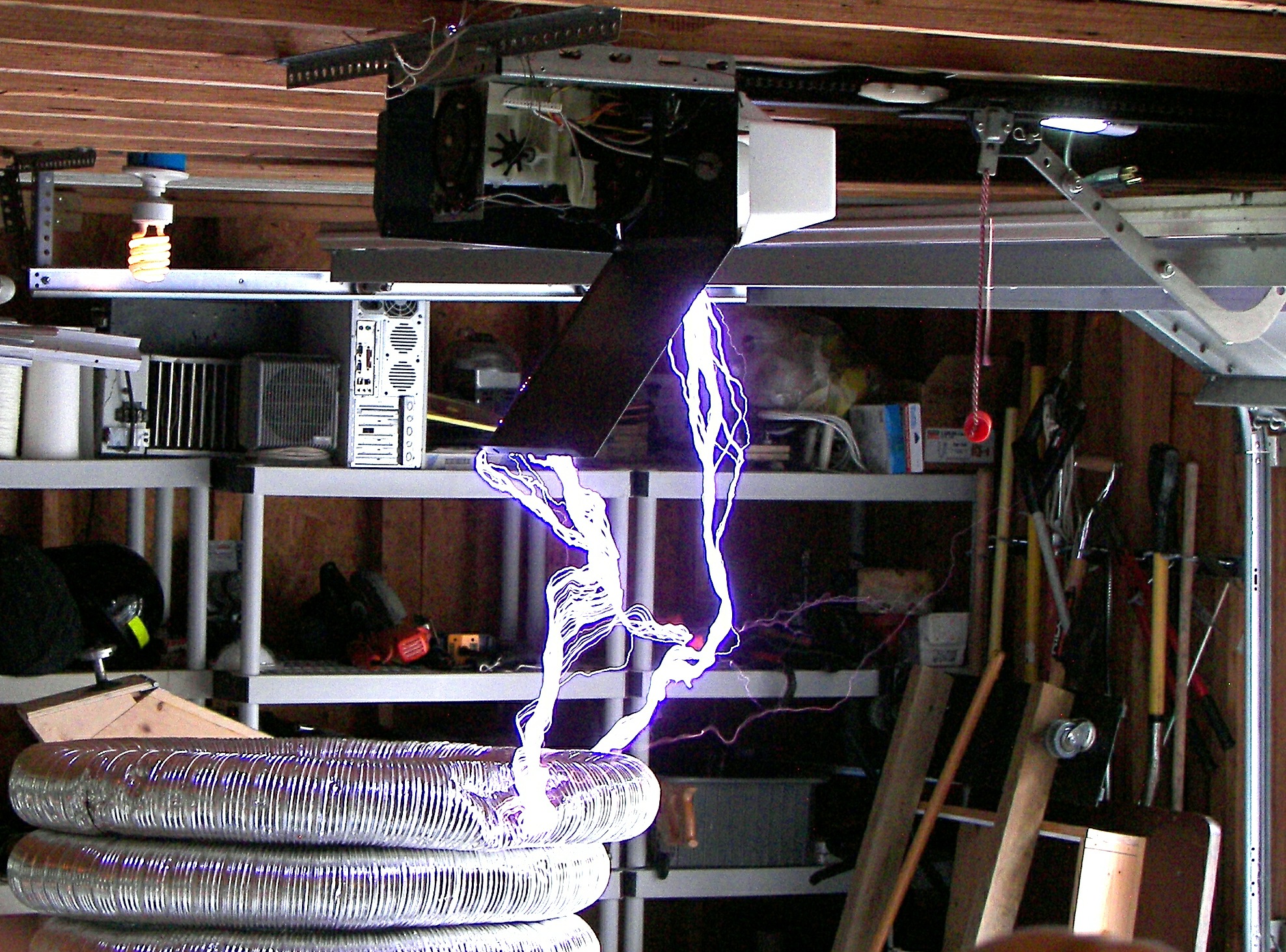
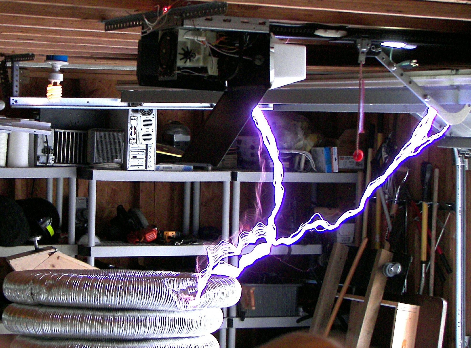
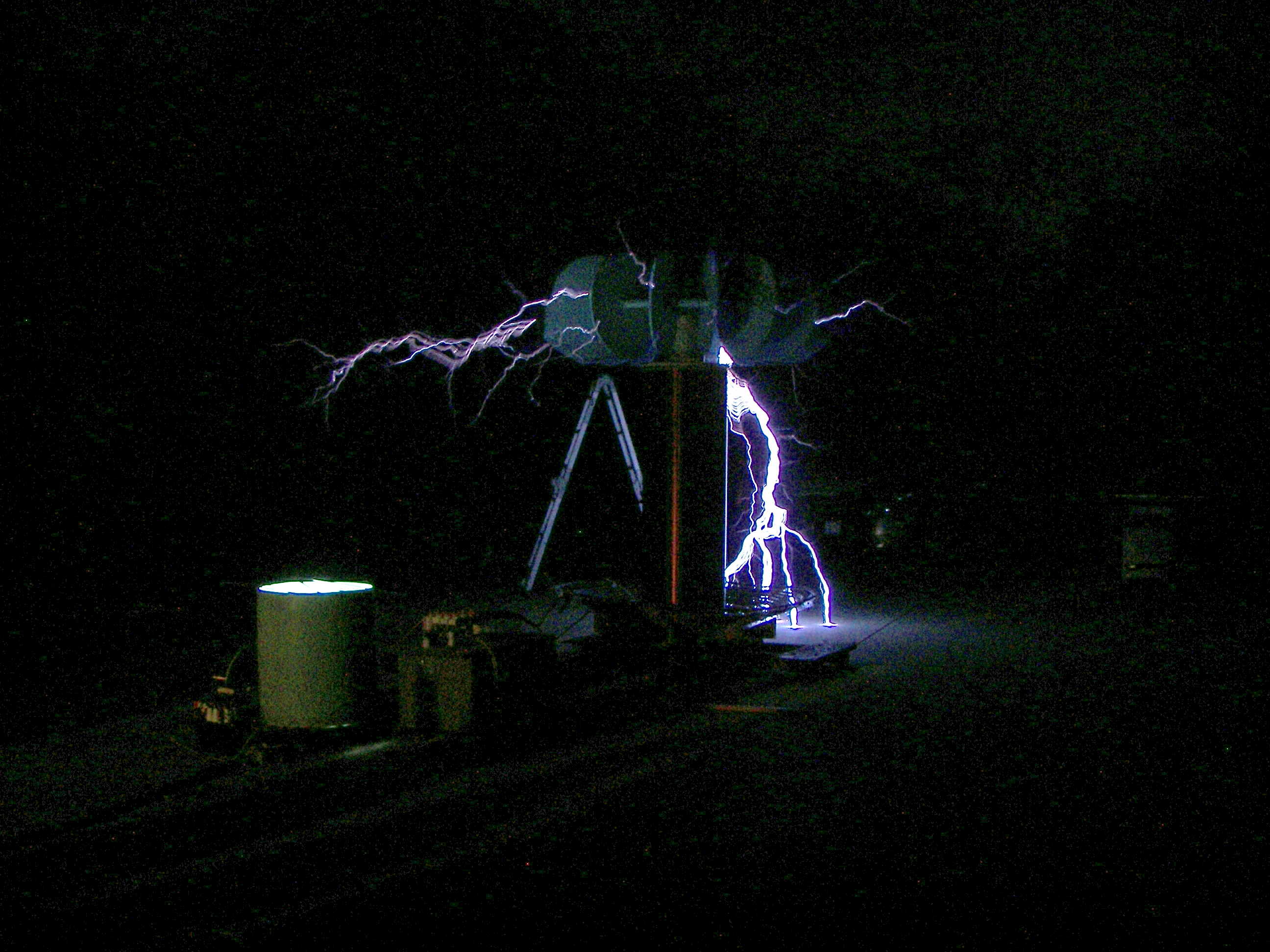
The next coil, which will be referred to as the "small TC", stood about 4 FT tall without the top load. After some tuning an the stacking of three top loads, it produced arcs of 4-5 ft. length which would seem to be well over a million volts. This coil was powered first by two neon sign transformers and then by a 13,500V potential transformer. The capacitors were maxwell type energy storage capacitors rated for 800Hz discharge. The cap was a variable speed rotary design. The coil was built by two teenagers under the direction of Mr. Pool and his learned associates. During the tuning, it was discovered that the overhead garage door had not been grounded. This resulting in an arc at the garage door motor and a small flame, which extinguished as soon as the power was removed. Once the door was grounded, the incident did not repeat. This coil made spectacular hot arcs.

The Hog TC
|

The Hog ballast
|

The Hog PSU
|

The Hog Pole Pig
|

The Hog
|

The Hog
|

The Hog
|

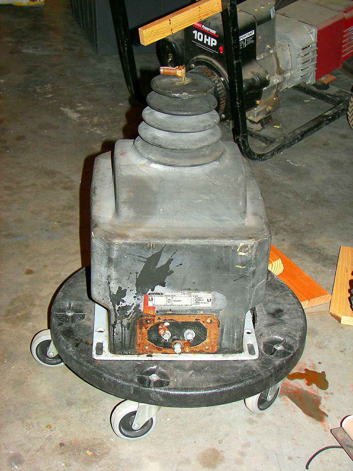
robust potential transformer
|
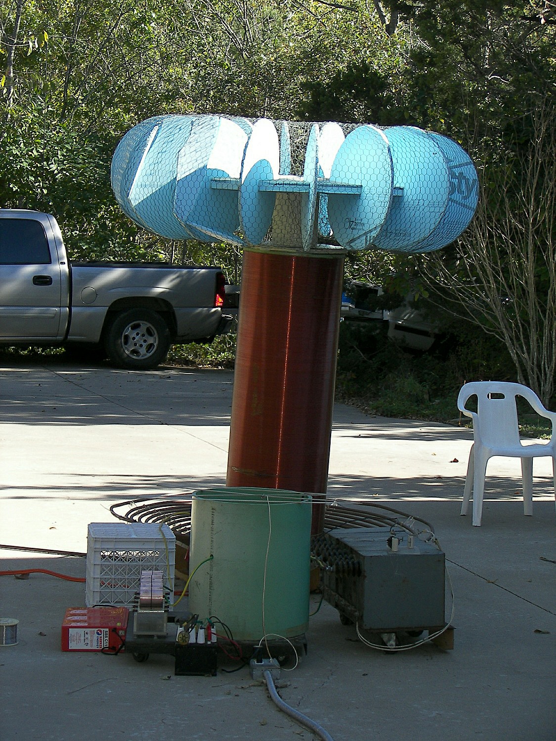
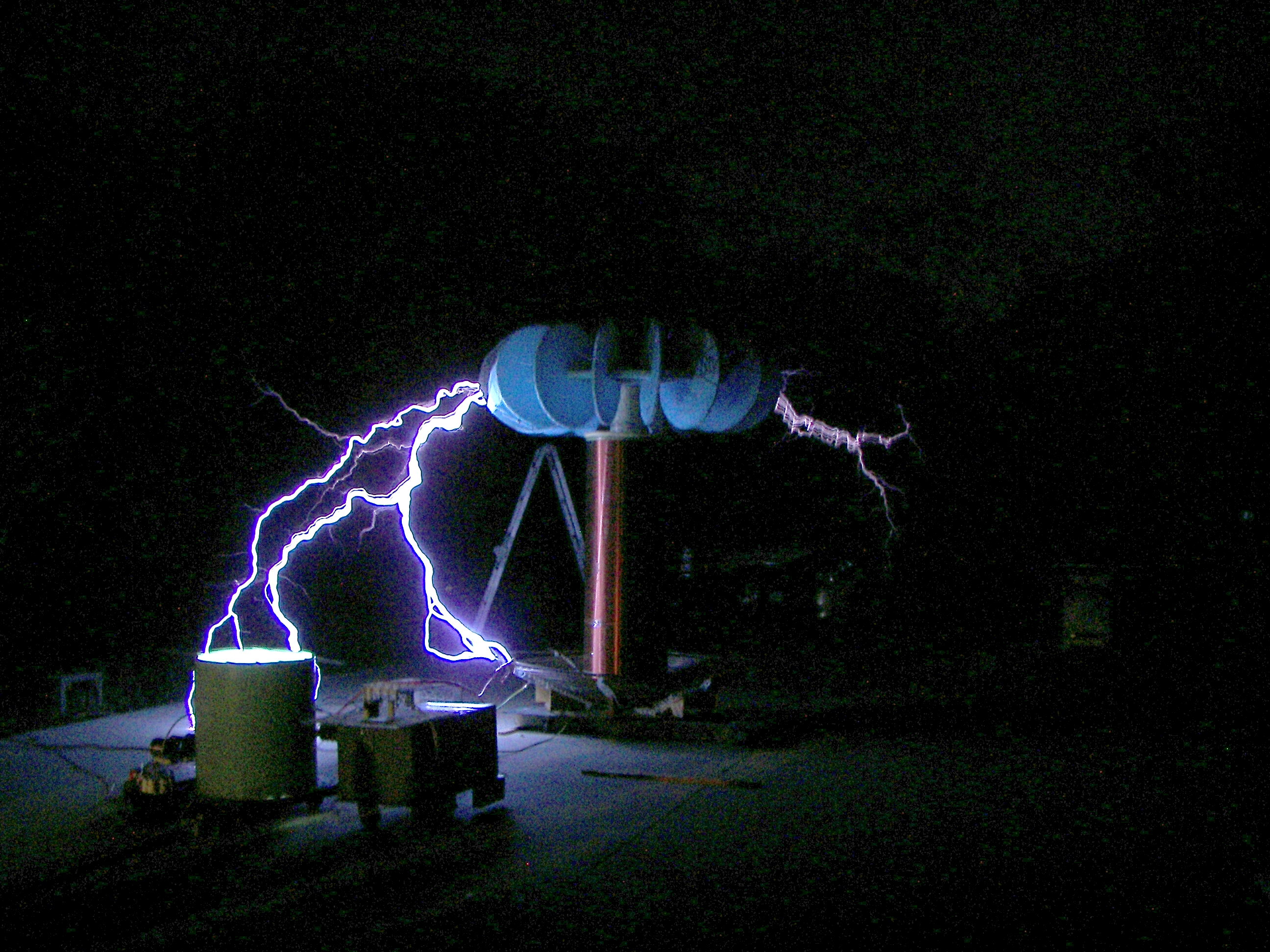
The largest coil, named "The Hog", had to be assembled outdoors due to its physical size. The secondary was about 24" diameter and over 6FT in height. It seems to be wound with #14 wire. The top load was some 4-5FT diameter. The images show the size of the ballast resistors and stack of variable autotransformers as well as the "pole pig" used to supply the high voltage to the primary. The arcs from this coil ocasionally reached 12 feet in length. Inside the green drum is the rotary gap. It uses a low voltage AC motor fed by an old transmitting-style VH rectifier filament transformer for insulation. Four large oil capacitors are stacked together near the gap. During one run, a 3" tall ceramic insulator used for suplying the primary coil was split right in half down the center of the long axis.
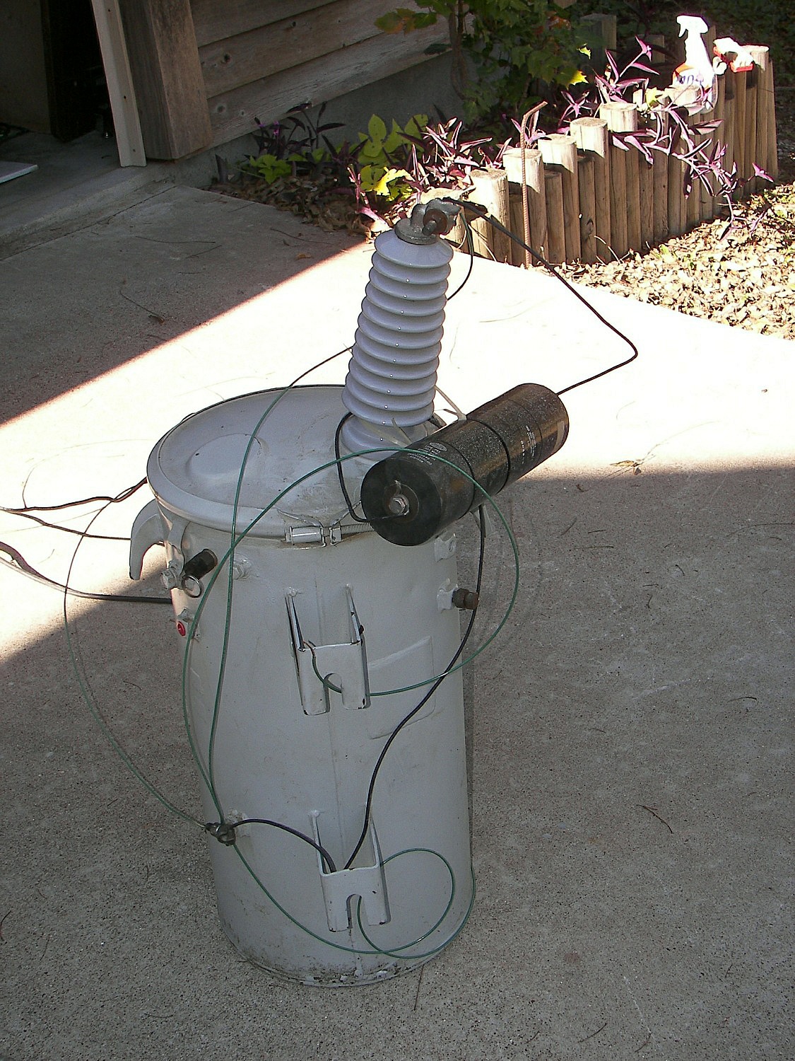
The last image shows a potential transformer. This kind of high powered unit is used to supply thousands of volts to whatever coil may need testing.
If you have read this far, then you deserve to see the videos. Some of them may be quite bad but nonetheless I guarantee large arcs and the like are to be seen in several. Here at the BunkerOfDoom, we always give you what you pay for!
Coin Shrinking Mainly a shot of the room as it is not good to put a camera in the chamber and expect to get it back in one piece. Some shrapnel can be seen on one of them flying out of the chamber.
quenching a gap What happens when a stream of air is directed at a spark gap with a powerful magnet on each side?
small TC As the coil is tuned up, the sparks just keep getting better.
The Hog Monstrous
Thanks for visting bunkerofdoom.com