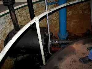
Here's the business end of one of the two hydraulic cylinders that controls the throttle vanes for one turbine. This is in the same room as the previous image. In this room also is the packing box for the shaft. Directly below the floor is the turbine itself, and above is a deck where the generator field brushes are installed.
|

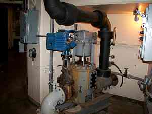
Part of the cooling system for a main unit. The lake water enters beow and passes through a strainer/scraper that cleans any goop out of the flow before it passes through the cooling coils.heat exchanger above. The water coming up to this is coming from the small end of the scroll case deep under the floor. No pump is required because this is below lake level.
|

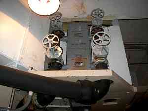
Looking toward the ceiling, the heat exchanger inlets can be seen. A valve on each one allows them to be individually controlled, or shut off for maintenance while keeping the unit online. That assembly is level with the rotating field and air is blown through it to cool the generator. The heat exchanger casing is visible from above in the shaft pick photos.
|