
tkpsufront.jpg
892 x 625
tkpwrcrtl.jpg
975 x 666
tuckerkefront2.jpg
496 x 1102

tuckerkwfront1.jpg
540 x 1096
This page gives a short text description of the controls. Details and pictures follow on the next page.
|
tkpsufront.jpg 892 x 625 |
tkpwrcrtl.jpg 975 x 666 |
tuckerkefront2.jpg 496 x 1102 |
tuckerkwfront1.jpg 540 x 1096 |
The images show:
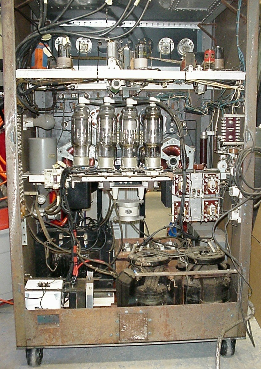
1. the power supply area from the front including the four sockets for the rectifier tubes, the rectifier filament transformers below them, the final and modulator chokes to the left, and the space to the right, where the modulation transformer goes. The transformer is very heavy and will be moved shortly.
DETOUR: It was decided to move the rectifiers to the rear of the unit, behind the modulator tubes. The filament transformers and broken chokes were also removed from this area in order to clean it out.
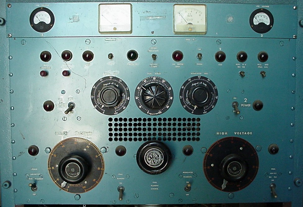
2. The power supply operating control panel. Controls from left to right are:
-TOP ROW:
PLATE OVERLOAD and RESET button,
G2 OVERLOAD and RESET button,
FUSE 1 indicator lamp,
TEST switch,
ON THE AIR indicator,
LOW/NORMAL power selector,
AIR SWITCH OPEN (blower interlock),
CW/PHONE switch,
FUSE 2 indicator lamp,
MOD HV RECT FIL indicator and switch,
MOD AND FINAL BIAS indicator and switch.
-MIDDLE ROW:
POWER 1 indicator,
POWER 1 switch,
FINAL BIAS adjustment,
FINAL SCREEN adjustment,
MOD BIAS adjustment,
POWER 2 switch,
POWER 2 indicator.
-BOTTOM ROW:
FAN/BIAS/MOD FIL's indicator and switch,
FINAL HV adjustment,
FINAL FILAMENT indicator and switch,
FINAL FILAMENT adjustment,
MODULATOR FILAMENT indicator and switch,
MODULATOR HV adjustment,
FINAL HV RECT FILAMENT indicator and switch.
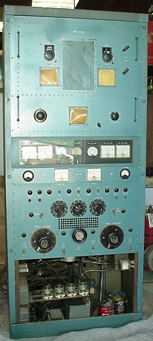
3., 4. The front view of the transmitter in its entirety.
Page 27 of 28