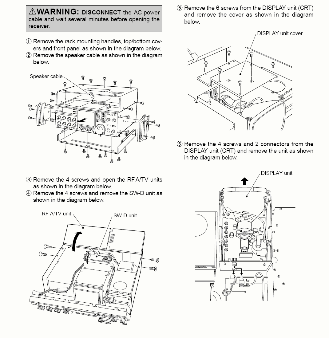
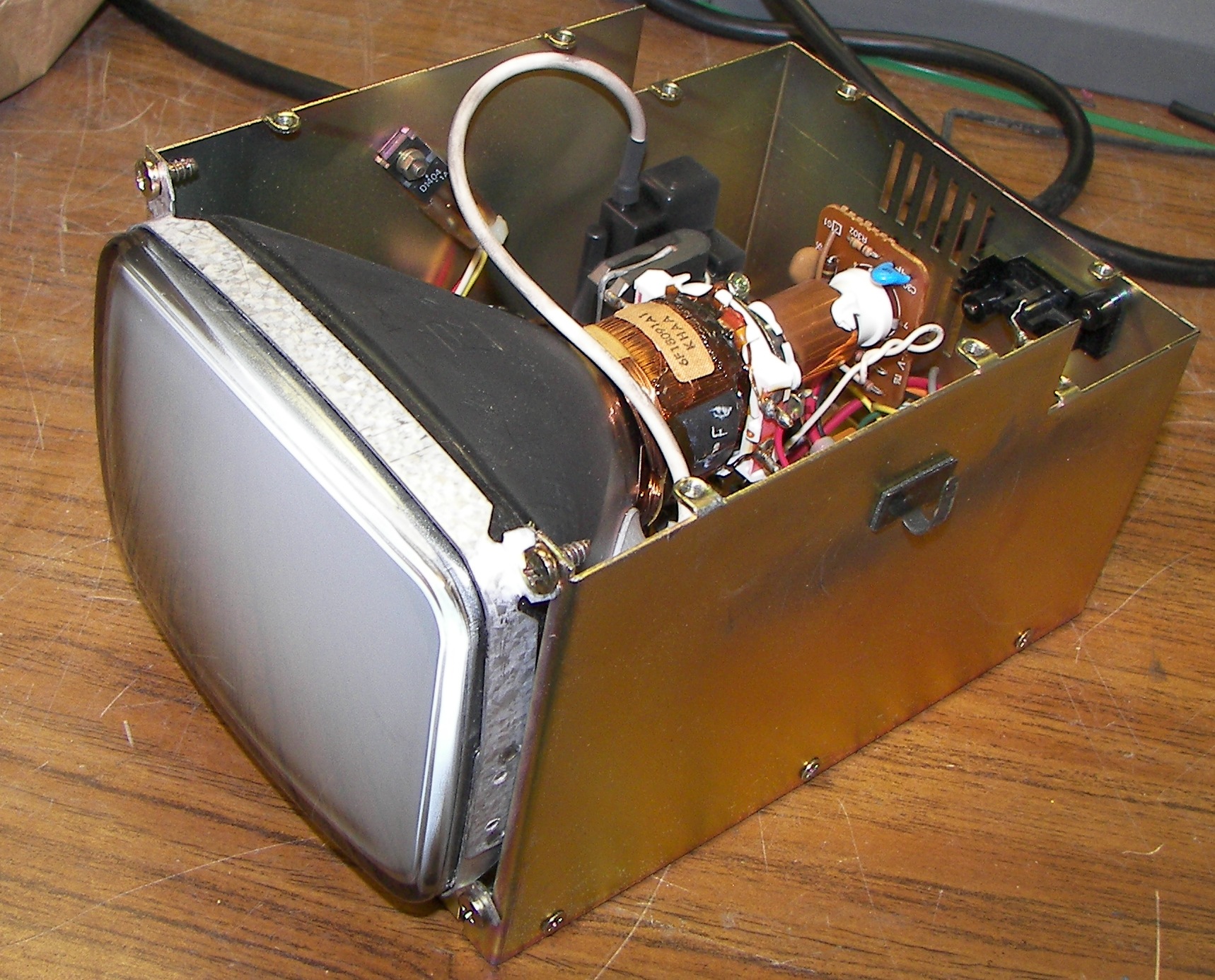
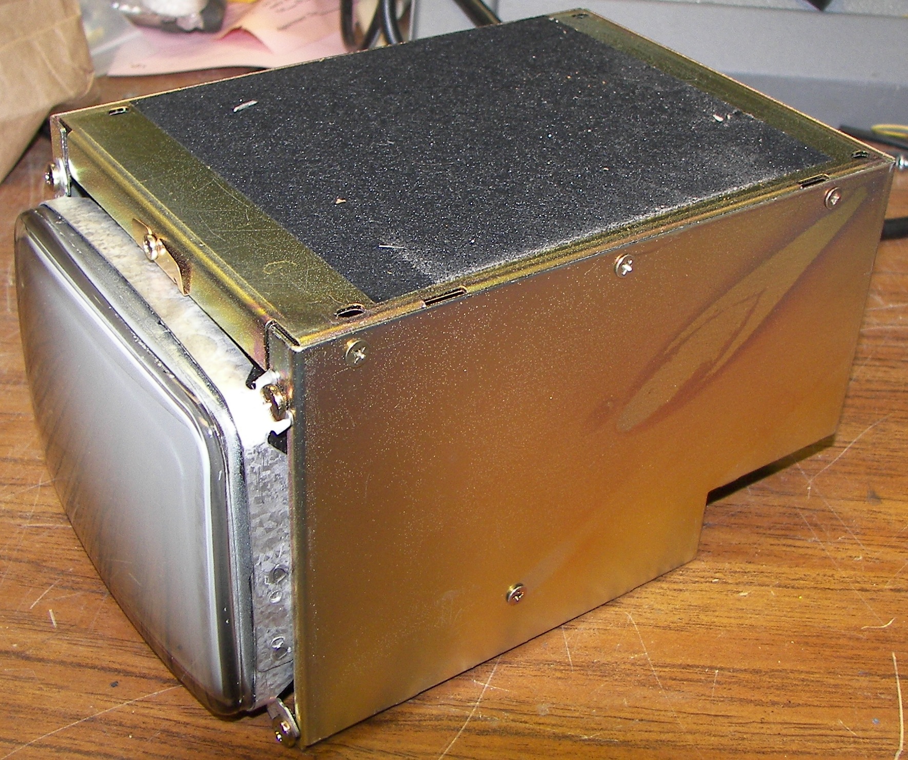
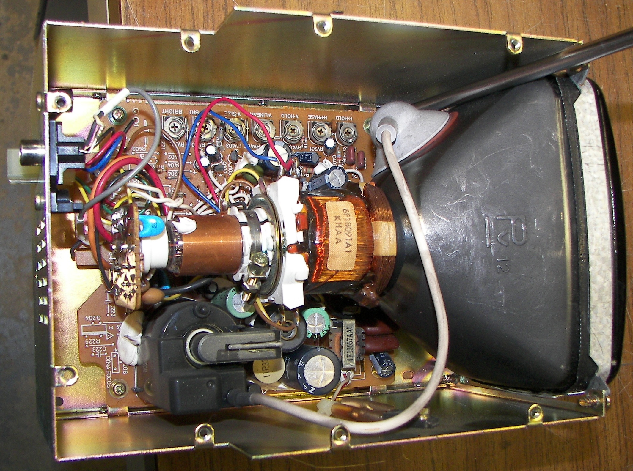
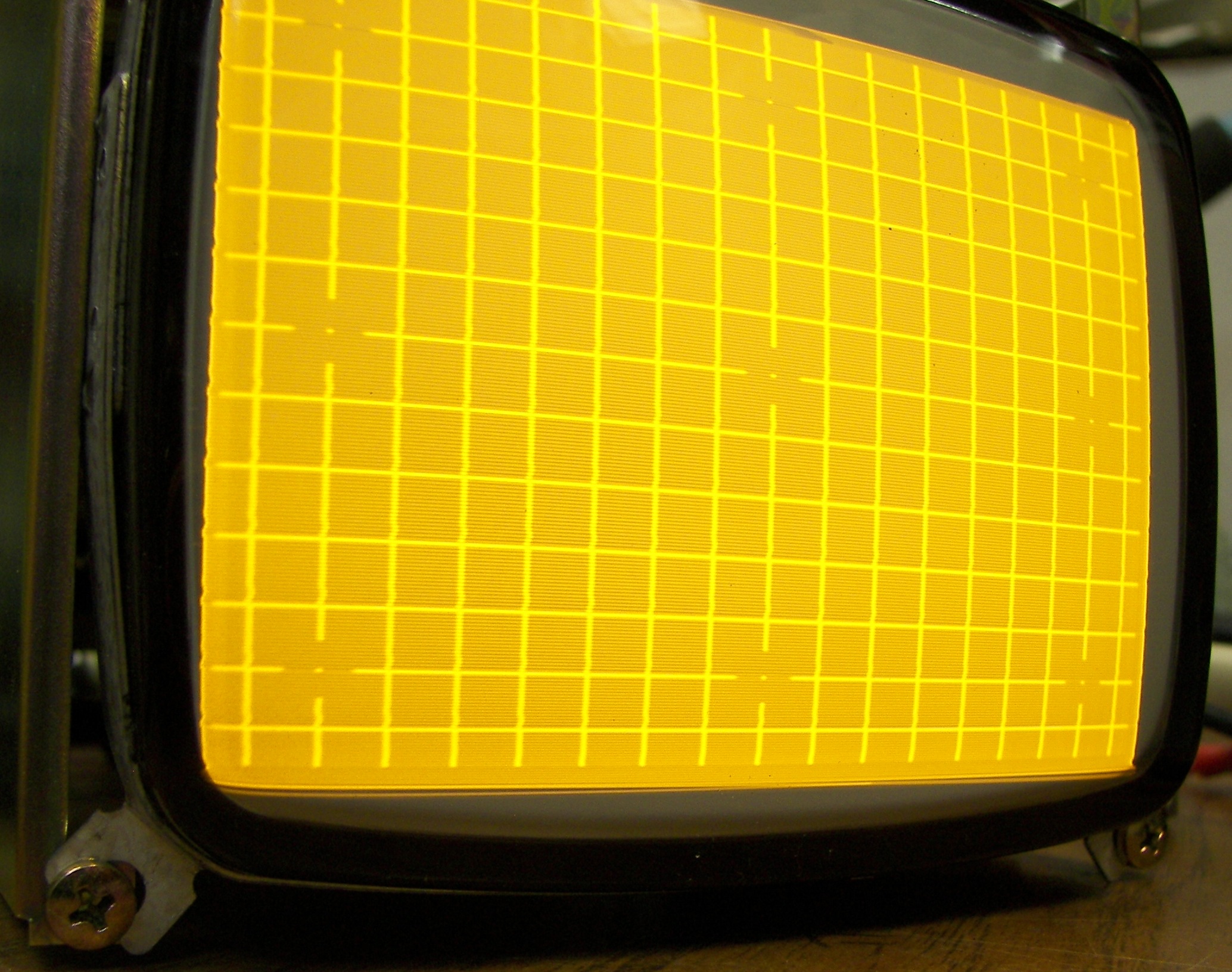
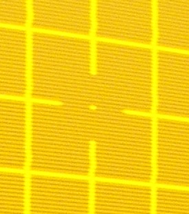
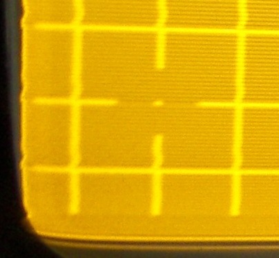
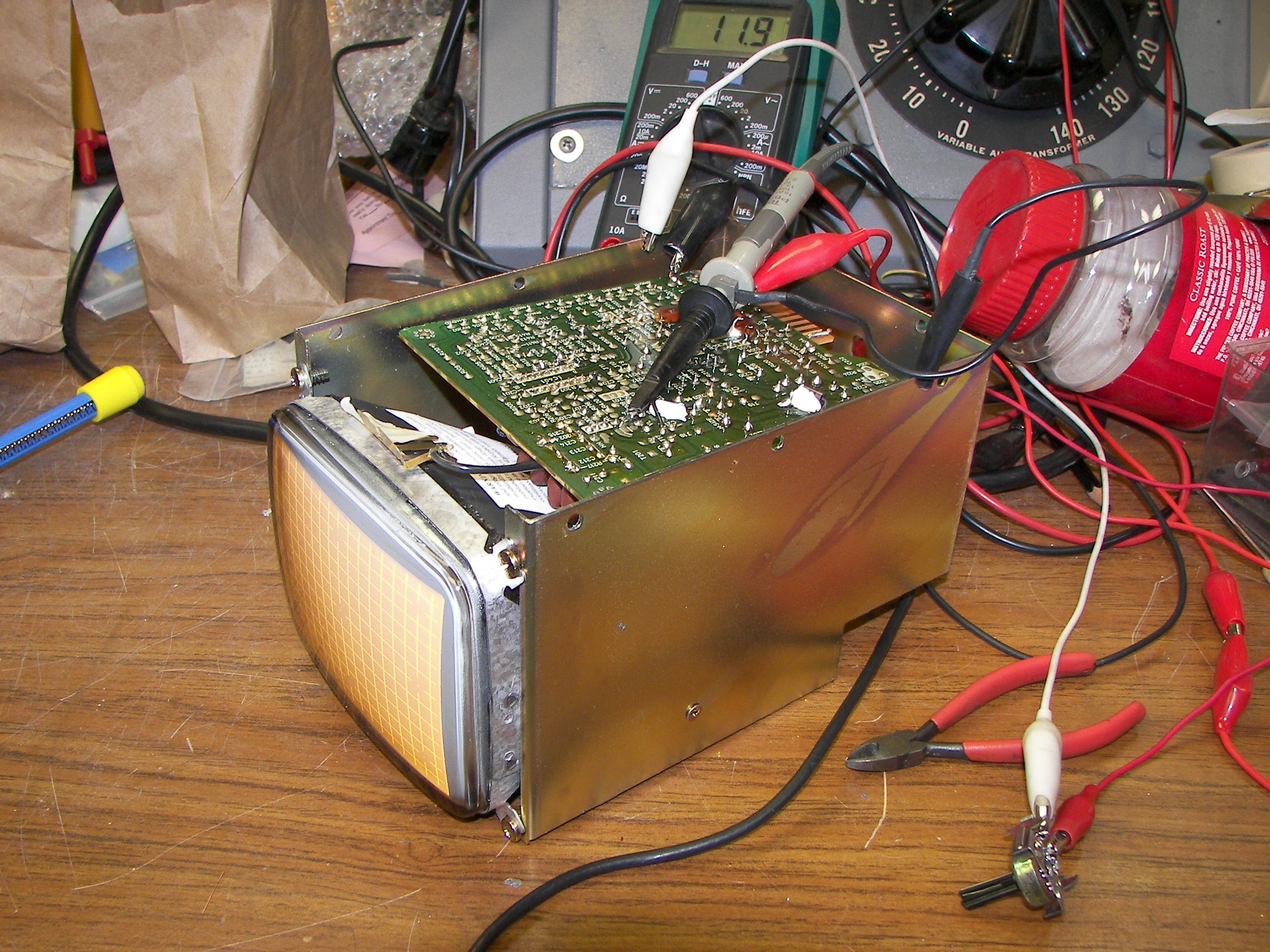
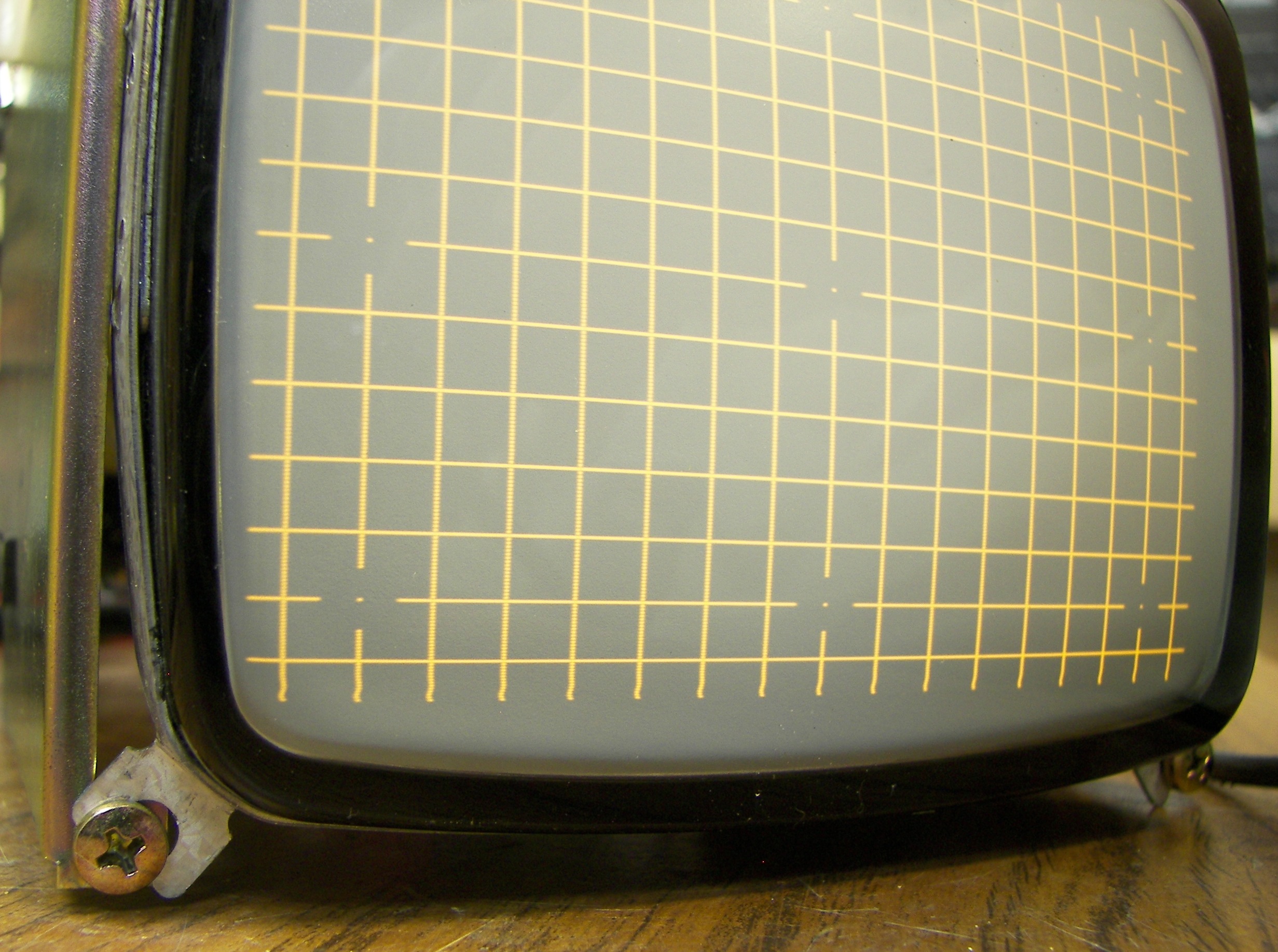
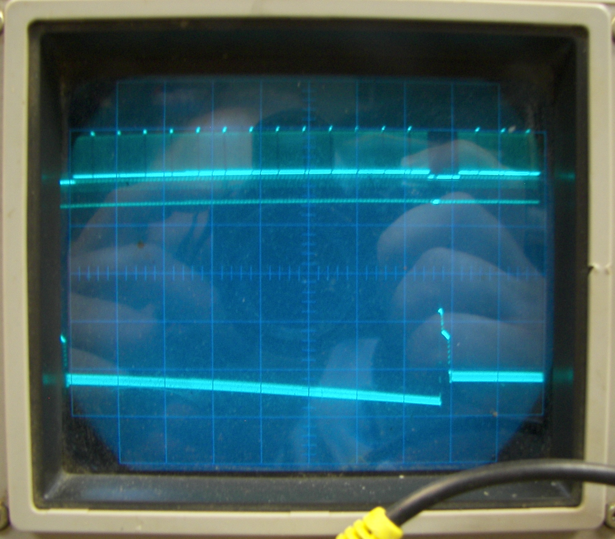
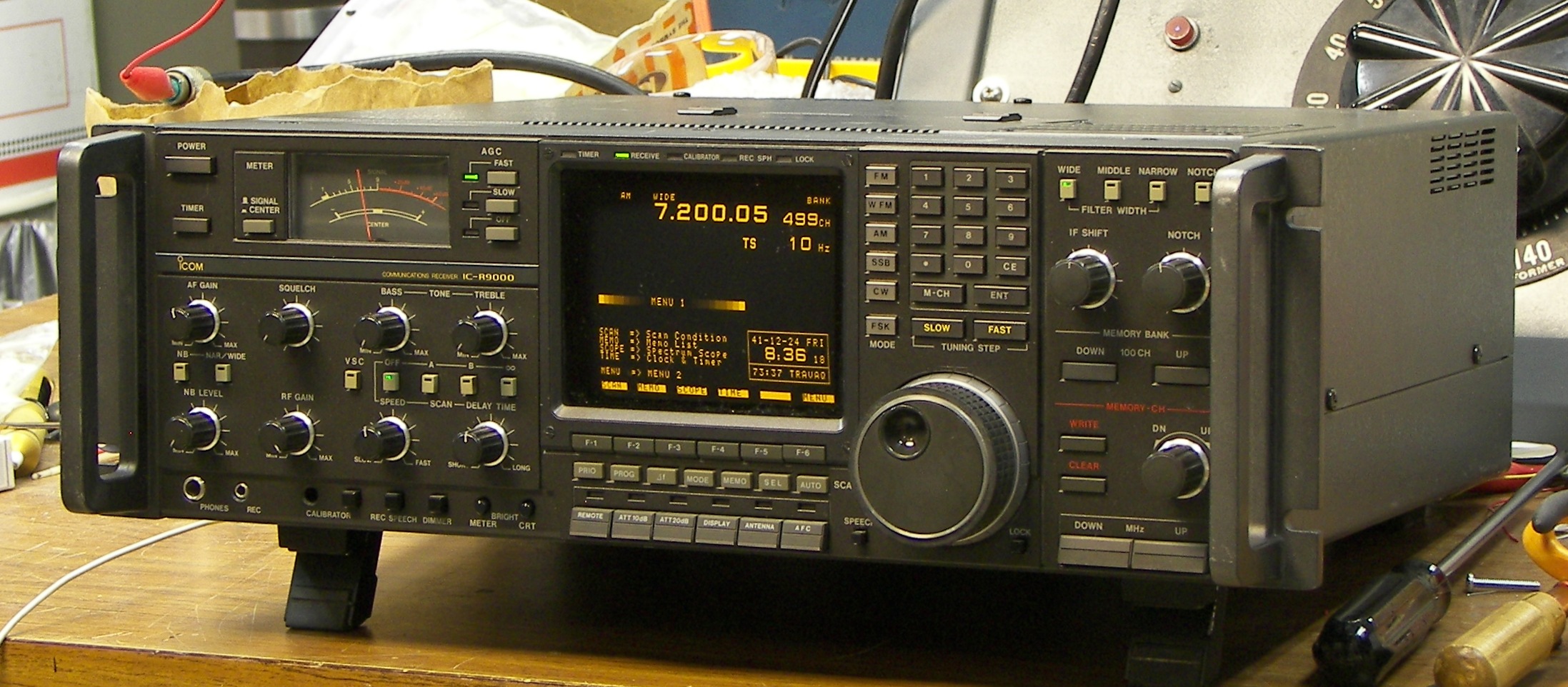

The most common issues for a CRT based display with vertical deflection problems will show any of these symproms:
1.) A short picture that won't evenly fill the screen from top to bottom.
2.) A picture that seems compressed or "folded over" at the top.
3.) A picture in which some items are stretched or off the screen.
There are two components that usually cause these symptoms in a CRT-based monitor.
The first is the DC blocking capacitor, usually in the return side of the deflection yoke circuit. When it loses capacitance, its resistance increases and the picture cannot go to full height. In this monitor you should be able to adjust the height so the scan area can be extended well above and below the screen area. Not that you would do that, but it needs the capability in order to function properly.
The second problem relates more to the "fold-over" symptom. There is a capacitor that is charged every trace (picture scan from top to bottom), and discharged upon retrace (the quick time during which the electron beam is returned to the top for another scan, and should be blanked out). The charge in this capacitor adds a boost to the retrace pulse to snap the beam back to the top of the screen. If this capacitor is weak, it won't hold enough charge to do the job, the beam will return slowly and become unblanked before it gets back to the top of the screen. The blanking time is fixed, and a function of the timing information embedded in the video signal, whether the monitor's sweep circuits cope with it or not.
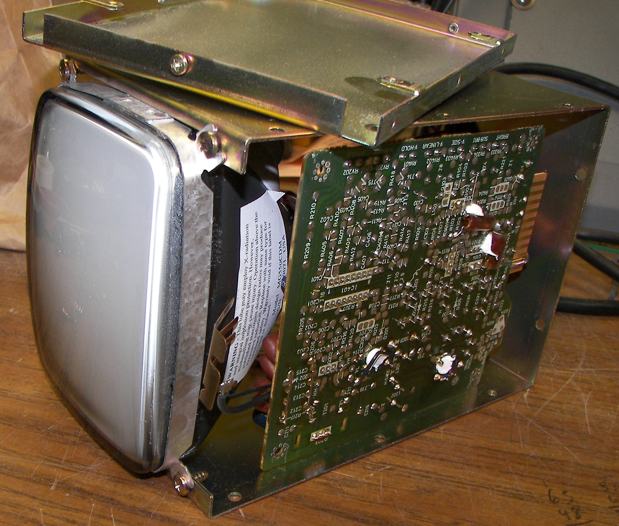
The capacitors to replace are C407 and C410. Be sure to use caps rated for the same capacitance, 85 or 105 deg C, and low-ESR ones if possible. Using caps rated for higher voltages is also helpful. You don't want to have to take this all apart again.
While it is apart, check and resolder the connections on the components listed below the table of images. They will sometimes have cracks in the solder due to vibrations from the constant high frequency/high current deflection signals, or just from heat. In general, look for circular cracks in the solder around the pins of any component that extend through the board. Resolder them.
Components to resolder (where leads pass through board):
To do the following steps, use the owners manual for guidance on operating the radio and connecting signals to it.
setting the geometry, width, and centering:
Setting the brightness and contrast:
If any part of this is unclear, consult an electronics expert. I disclaim liability for everything from the beginning of time until the end of time.
Patrick Jankowiak KD5OEI