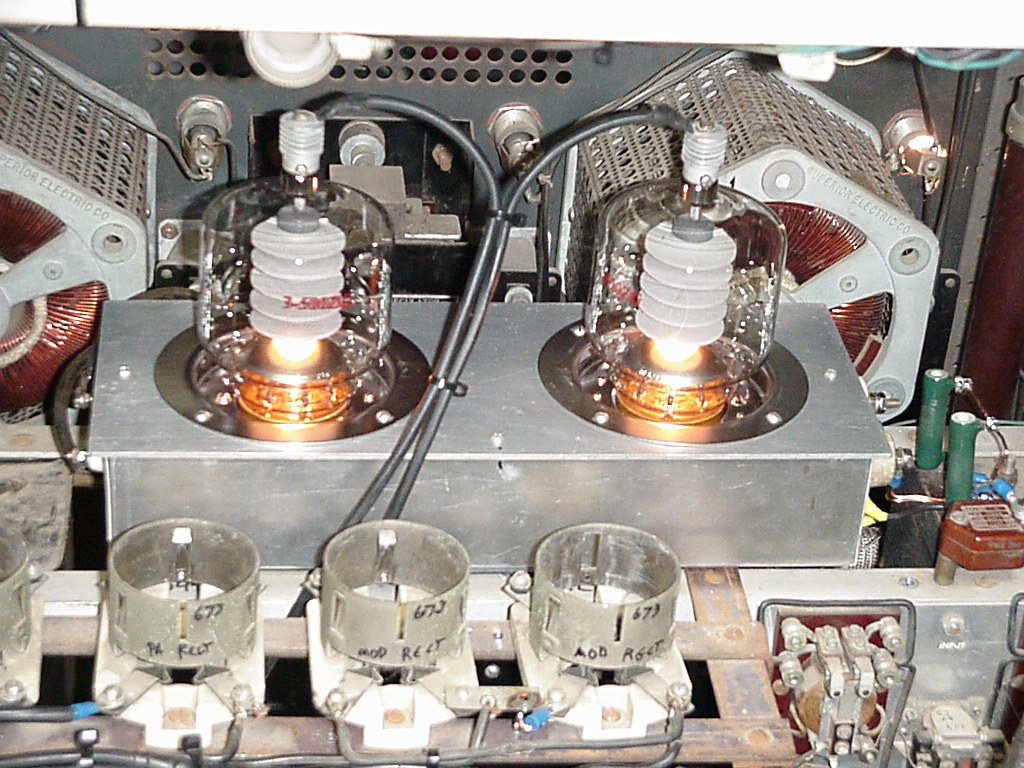
Little explanation is needed here.. The 'fire bottles' seem at home! Before any real testing is done, I'll find a pair of chimneys and mounting hardware, so they'll stay nice and cool. Preliminarily, 3KV was applied, and a plate current of 200mA was noted. The 3-500Z is designed for zero-bias operation. It required only a very few volts of bias to reduce the plate current to 100mA, so indeed the modulator bias supply will be visited, and its range of 0-200V will be reduced to about 0-20V to allow the use of more than the bottom 5% of the bias adjustment variac.
At this point, while running the HV at 3KV, PA current at 200mA, and doing the same with the modulator current, the 20A circuit breaker feeding the 120VAC outlet from which the KW was drawing its power opened. Before proceeding with the rework of the HV power supply's rectifier and primary circuits, it's time to install the 230V outlet in the lab's power cabinet and do the same with a plug on the KW's power cord. As found, it has two 120VAC plugs on it. These were both plugged into a 120V outlet for tests. These would have been normally plugged into two separately wired 115V outlets for 230V as was originally done, but it's best to go ahead and make the change for safety considerations.
Page 36