site top page |Begin Transmitter Examination|Previous Page|
The grid current meter on the main metering panel of the transmitter was 7mA FS, but 100mA FSR. It required a 1 Ohm resistance in parallel with the movement in order to bring the scale true. It is not known why this had not seemed to have been done, as 7mA is not much grid current for a 4-1000 under the KW input rule. It is possible it had been mounted elsewhere and subsequently lost. It is also possible that it had been removed because at one time the transmitter was said to have been used as a linear amplifier which is certainly practial given the degree to which the plate voltage could be increased in the original design.
On one of the front panels of the transmitter cabinet devoted to switching, the normal/test momentary switch was replaced because it had bad contacts. This was used for keying the transmitter momentarily from the front panel. I used a center-off on-off-momentary DPDT switch so that when the key is down, it can be keyed continuously (normal when the key is locked down), on standby (middle pos.), or keyed momentarily regardless of the key position. This extra position is important because of having only two hands.
The Final Bias power supply was also repaired. It had burned the bleeder resistors and those were replaced with higher wattage units. The heavy bleed of approximately 100mA was preserved.
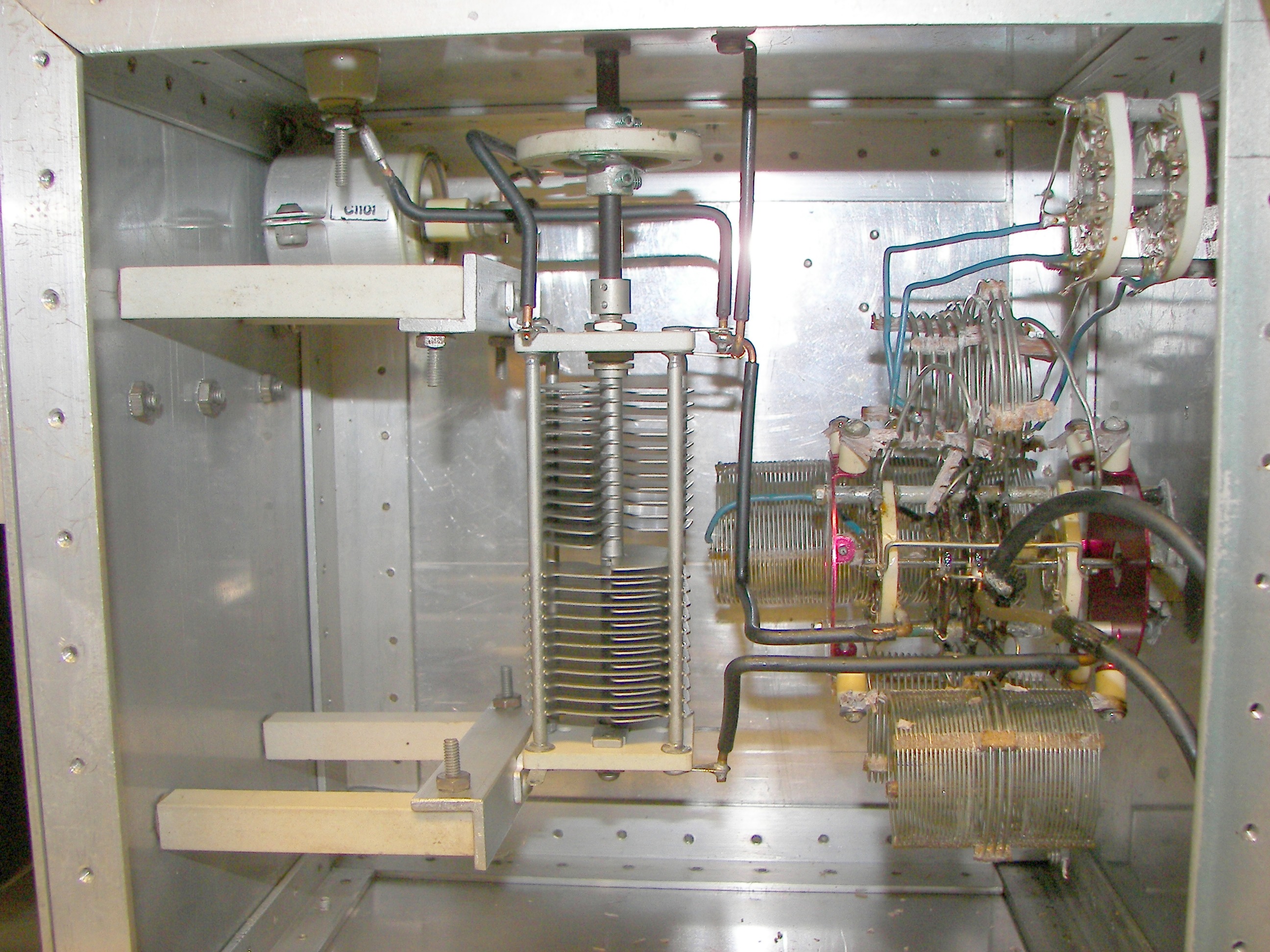
Inside the RF deck, it was found that the "B&W JTCL 10-80" coil turret assy used for the input tuning was ruined from old age of 60 years. The sort of plastic used for holding the coils in shape is claimed to be hygroscopic and after so long in service had turned partially to dust. 60 years of service is cause for no complaint.
The coil set was removed along with a 90 degree drive and a dual section tuning capacitor and all of this was replaced with a National MB-40 tuning unit. The MB-40 tunes the full range across the 10-80 ham bands in 1/2 turn of the shaft. A vernier is used for fine tuning. The MB-40 uses ceramic coil forms. The number of turns on the MB-40 link was set to 4T for a match with approximately 50 Ohms when found. The old B&W coils and switch were given to W5FRS, he might use parts from, or rebuild the assy.
The 56 Ohm 2W carbon resistor previously put in series with the grid lead while investigating the parastic was the cause of the next issue. During tune-up tests undertaken with the MB-40 in place, the resistor eventually burned up. It should have been removed before and should not be necessary.
Driving with an IC-735, these figures were obtained before the resistor burned in half:
F = 7220KC
MB-40 dial = 15 (my dial is reversed so that is "85" by the book.
RF output = 800W
Plate voltage = 3000V
Plate current = 340mA
Plate DC Input = 1020W
Plate efficiency = 78.5%
Grid Bias = -160V
Grid current = 30mA
Grid DC input = 4.8W
Screen voltage - 380V
Screen current = 85mA
Screen DC input = 32.5W
Total DC input = 1060W
Drive = 28W (forward power)
Drive SWR - 1.7:1
Filament Voltage = 7.5V
Filament Current = 21A
Filament input = 157.5W
Total apparent input = 1245.5W
Total apparent efficiency = 64%
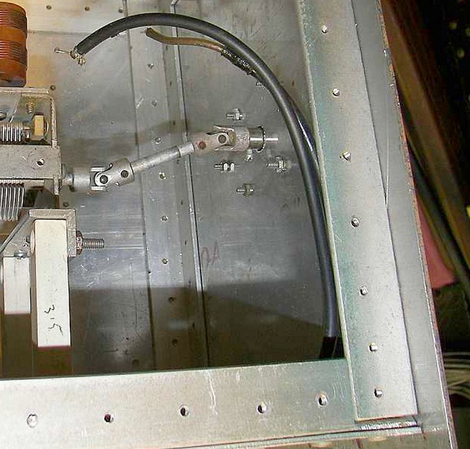
The MB-40 has an adjustable drive link. It may be swung in an arc so that it is either concentric to the MB-40's coils or out beside them. In view of the 1.7:1 SWR, it would be as well to add a control shaft (in the existing and now unused "10M-15M" switch hole) to permit this adjustment at the RF deck's front panel. 1.7:1 is acceptable but different conditions may benefit from a coupling adjustment as well as the tuning adjustment.
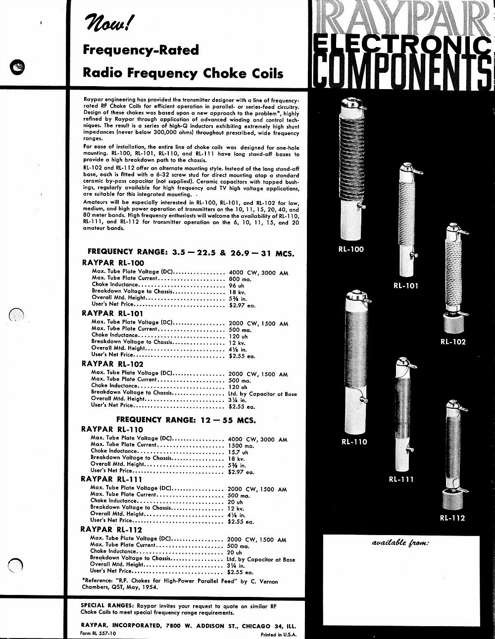
![]() Raypar RL-100 plate choke data. |
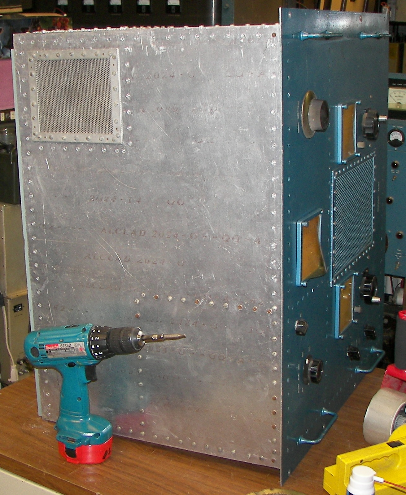
![]() many screws on the bottom panel of the RF deck. |
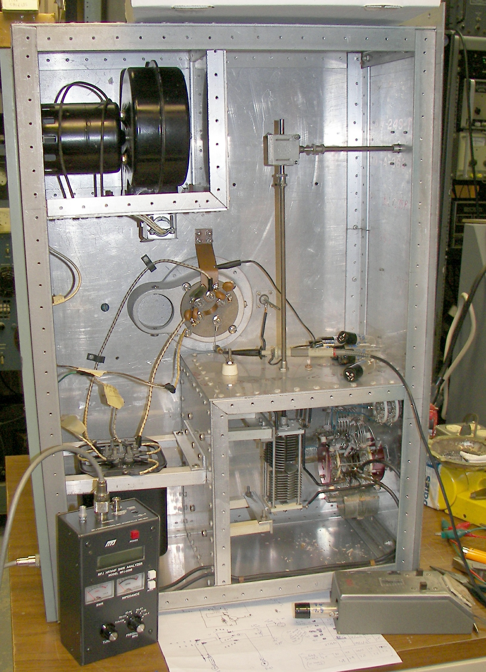
![]() bottom of the RF deck. |
![]() grid tuning compartment. upper left is neutralizing balance capacitor. This was kept in place. |
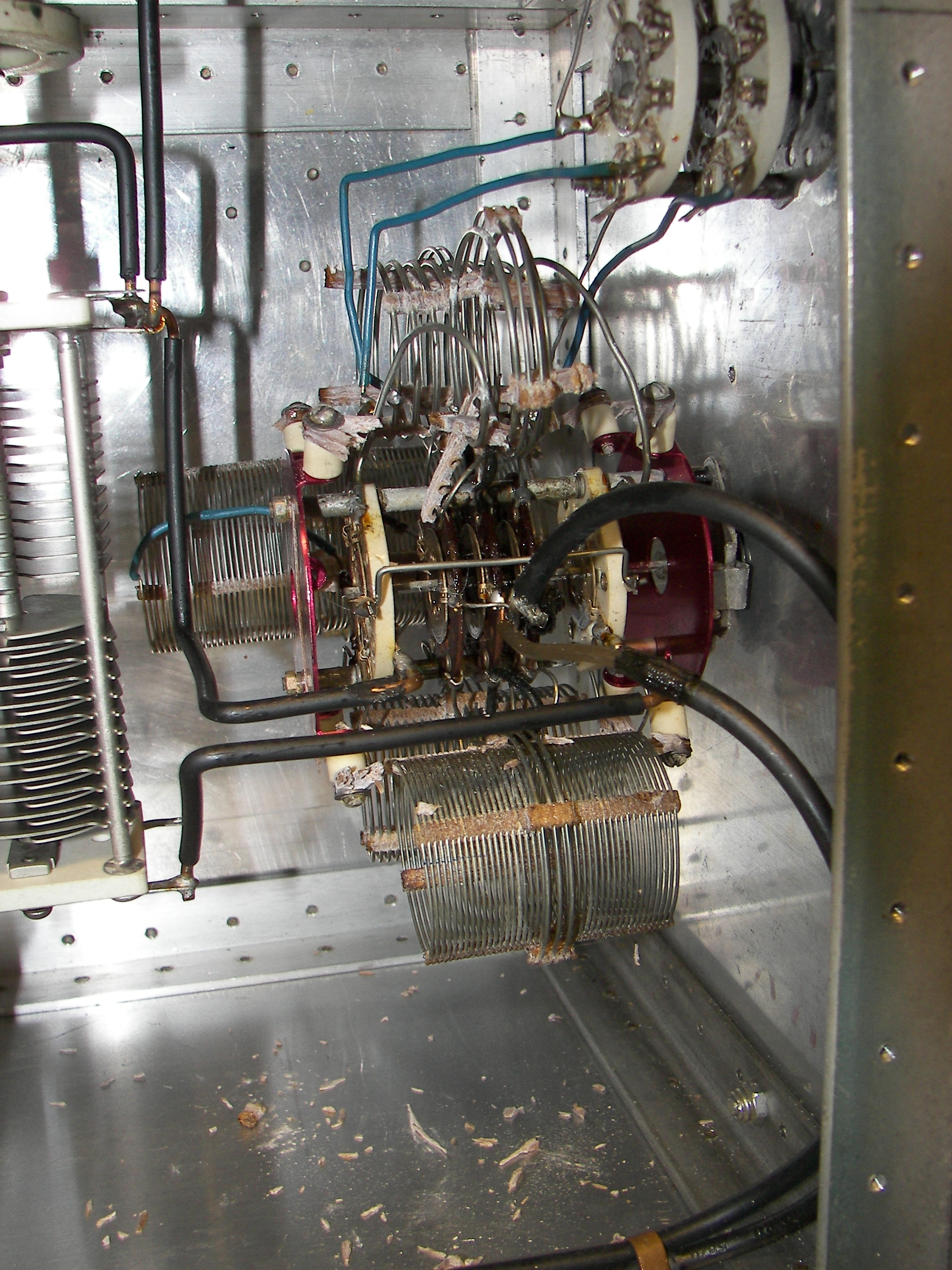
![]() grid tuning compartment. on 'floor' can be seen remains of coil supports. |
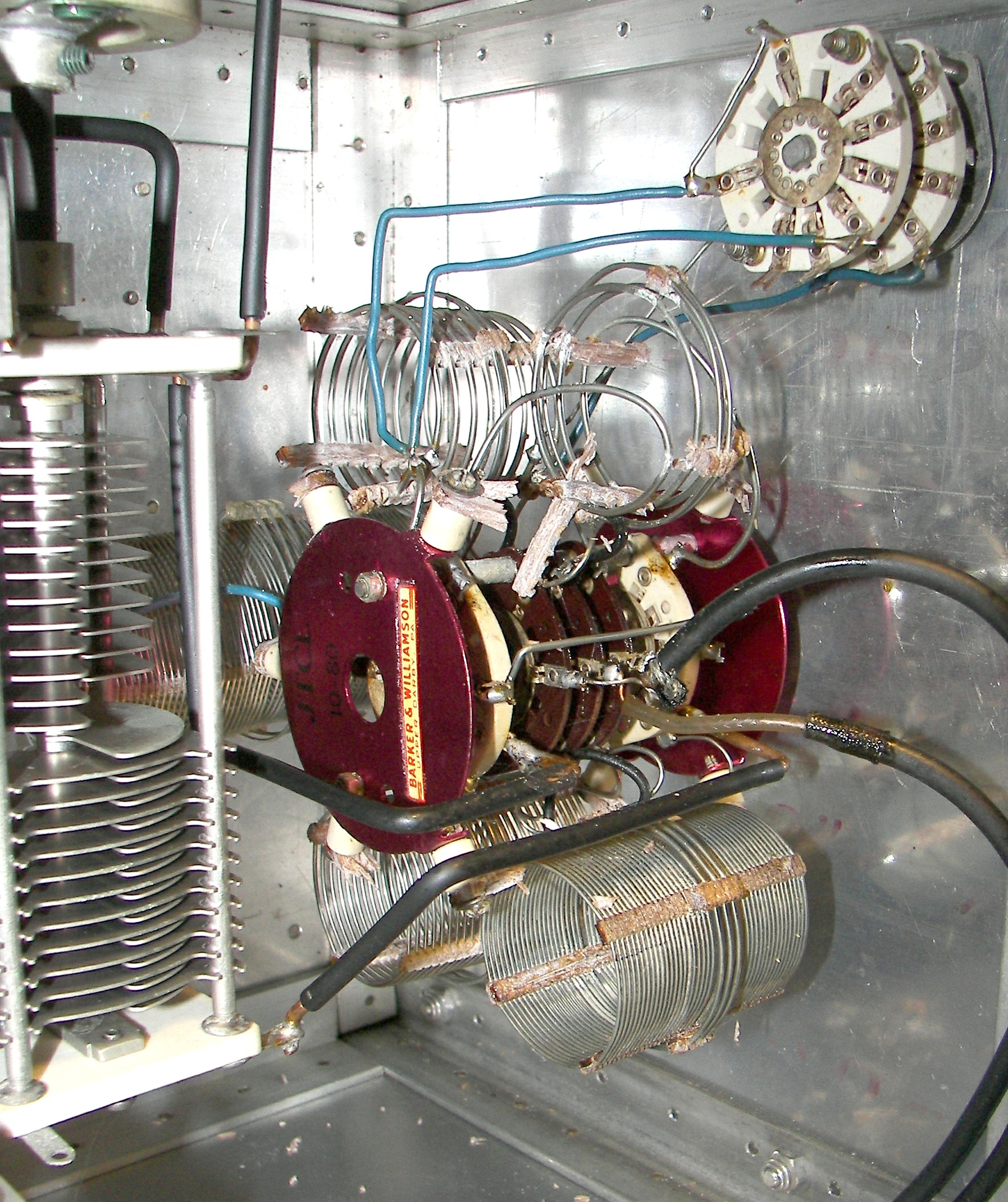
![]() grid tuning compartment. Top switch is the "10M-15M" selector. |
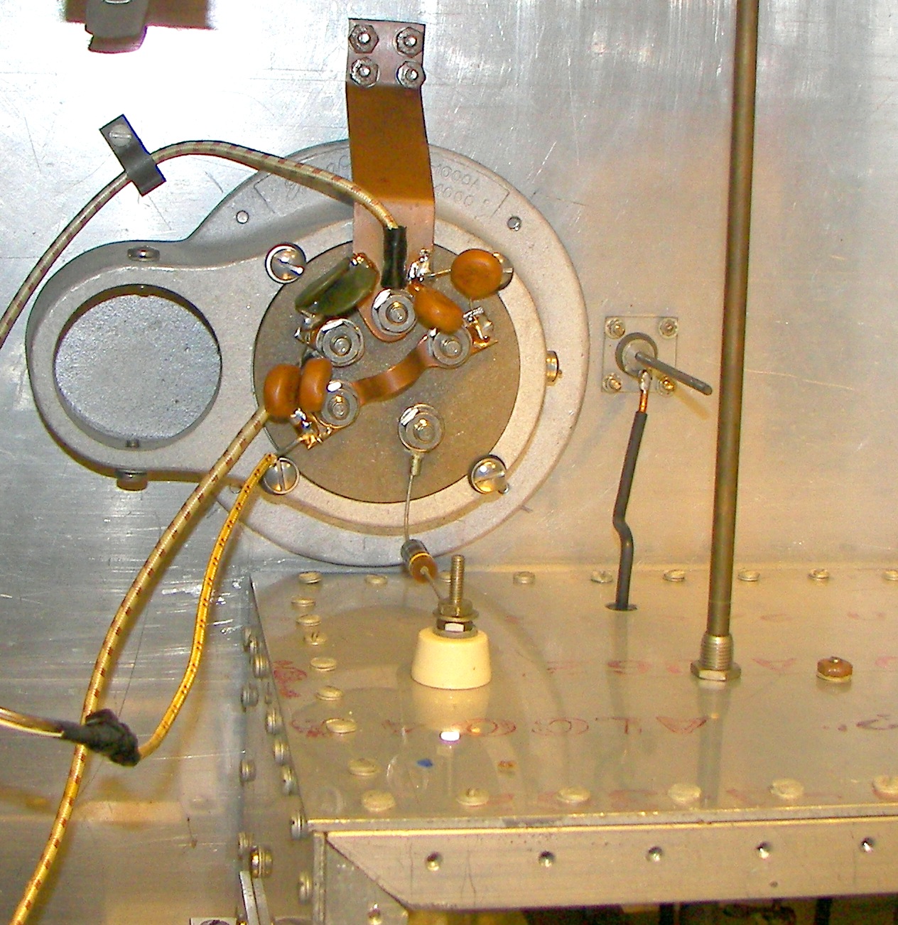
![]() under 4-1000 socket - note 56 Ohm 2W resistor, neutralizing probe, and strap from one side of filament to chassis. Note flexible strap between floating receptacles for 4-1000 G2 pins. |
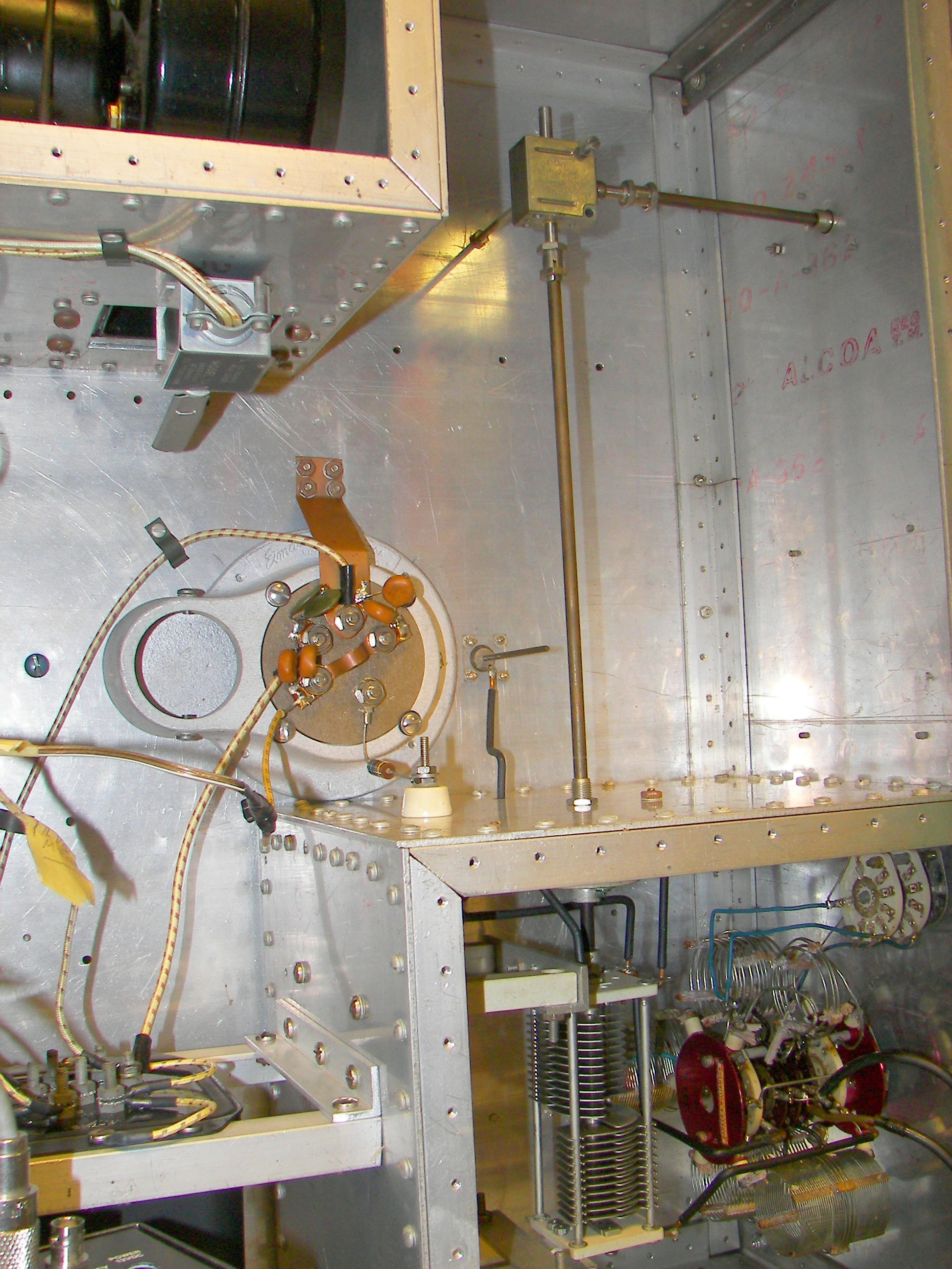
![]() under RF deck - 90 degree gearbox for original tuning capacitor can be seen. |
![]() top side of RF deck. The 20" strap (now removed) from anode to RF choke is visible. The four resistors at the plate side of the strap were also removed. The plate choke is now mounted from the roof of the enclosure so that its hot lead is within about 1" of the top copper plate of the blocking capacitors. |
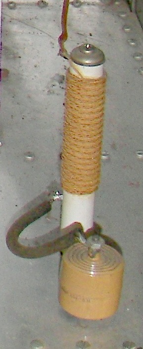
![]() Raypar RL-100 plate choke and RF bypass capacitor before being relocated. |
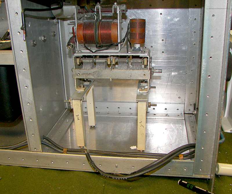
![]() test fit of MB-40 |
![]() The bolts of the vernier drive can be seen. |
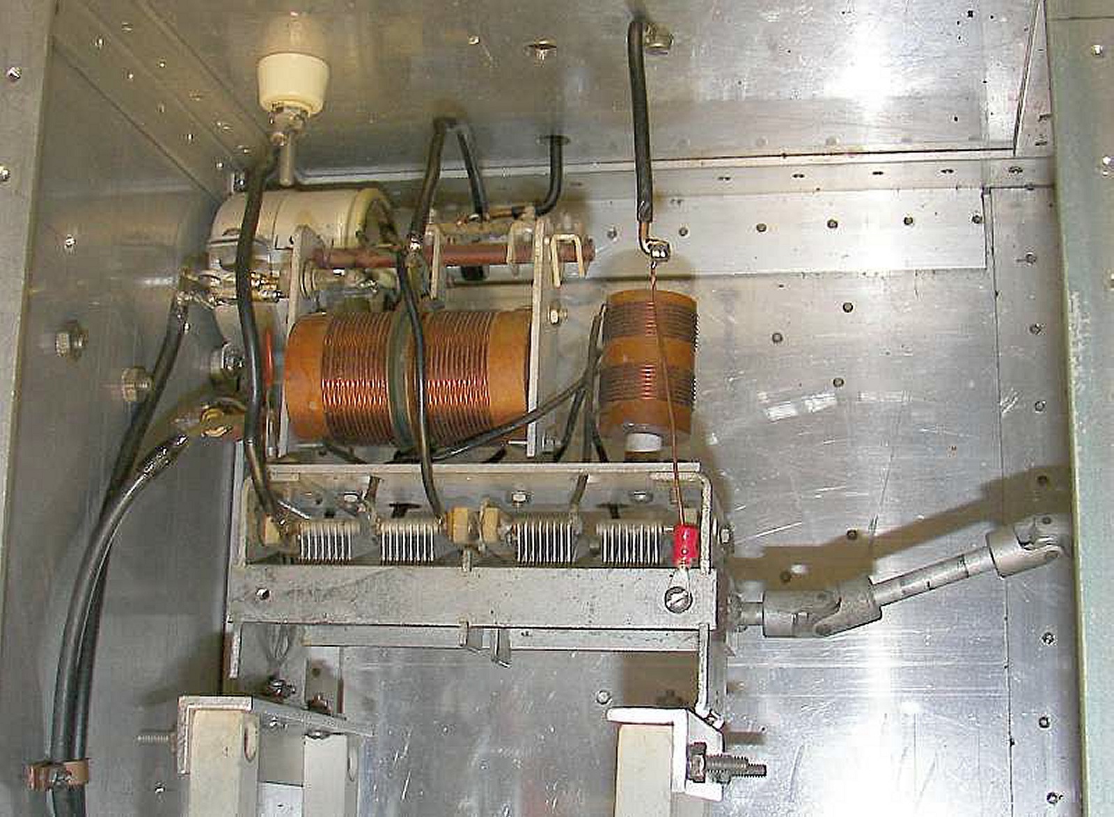
![]() when knobs don't align and no more holes are desired, U-joints are a cure that will avoid sloppy appearances. The movable link and its shaft can be seen near the top. A 1/4" wide, 1.25" long copper strap was added between the capacitor frame and rear wall. The longer, temporary small gauge wire was upgraded to a #14 all the way. It may have no benefit but seems to harm nothing. |

comparison of CG-512 modulator driver transformer to PA-512 modulator driver transformer. Electically alike, 40 watts rated. |
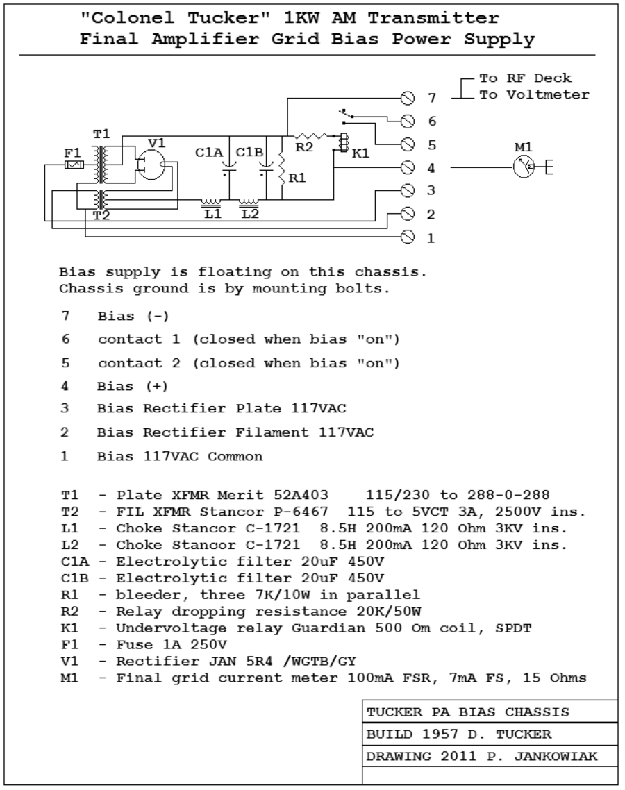
![]() schematic of Final grid bias supply (mounted in transmitter cabinet proper). |
Notes on the MB40 and MB150 tanks from the www. These things have been reprocessed and copied back and forth onto so many websites that it's not clear who posted them originally. MB-40 booklet MB-40 information MB-150 booklet MB-150 - GE Ham News here they are in one place.. |
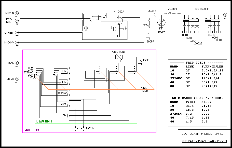
![]() RF deck grid tank "before". |
![]() RF deck grid tank "after" (not all other parts are shown). |
Page of