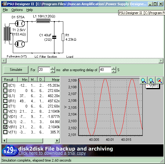
Output: 2143VDC @ 357mA with 8.37V ripple into a 6K load: 765 watts.
Output: 2105VDC @ 497mA with 8.37V ripple into a 4.23K load: 1046 watts.
Output: 2050VDC @ 695mA with 8.38V ripple into a 2.95K load: 1424 watts.
global top page |site top page |Begin Transmitter Examination|Previous Page|Next Page
After experimentation, it has been confirmed that the full wave center tap arrangement is possible, and that it produces voltages and currents close to those shown in the calculations on the previous page. It has also become apparent that the 4-1000A will not operate efficiently in the 2000 volt range since the screen grid current will rise excessively as the plate voltage decreases to the 500 to 750V screen supply voltage during the RF cycle. The current through the tube must also be substantially higher at 2000V than at a more reasonable 3000V in order to provide the same power.
These simulations were run in order to arrive at the best combination of existing power supply components. The decision is to use a C-L-C filter to provide higher voltages and yet keep some measure of regulation and low ripple. A comparison was done by simulation first. Some of the data from similar calculations regarding the regulation is presented in a general form here in an article addressing regulation and modulation. The next two screen captures show the effect of moving part of the filter capacitance to the input side of the inductor.
Output: 2143VDC @ 357mA with 8.37V ripple into a 6K load: 765 watts.
Output: 2105VDC @ 497mA with 8.37V ripple into a 4.23K load: 1046 watts.
Output: 2050VDC @ 695mA with 8.38V ripple into a 2.95K load: 1424 watts.
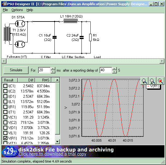
Output: 3174VDC @ 360mA with 516mV ripple into a 8.8K load: 1142 watts.
Output: 3071VDC @ 512mA with 719mV ripple into a 6K load: 1572 watts.
Output: 2956VDC @ 698.8mA with 961mV ripple into a 4.23K load: 2063 watts.
Next, tests will be run with this new C-L-C configuration to confirm the results.
Page 38