
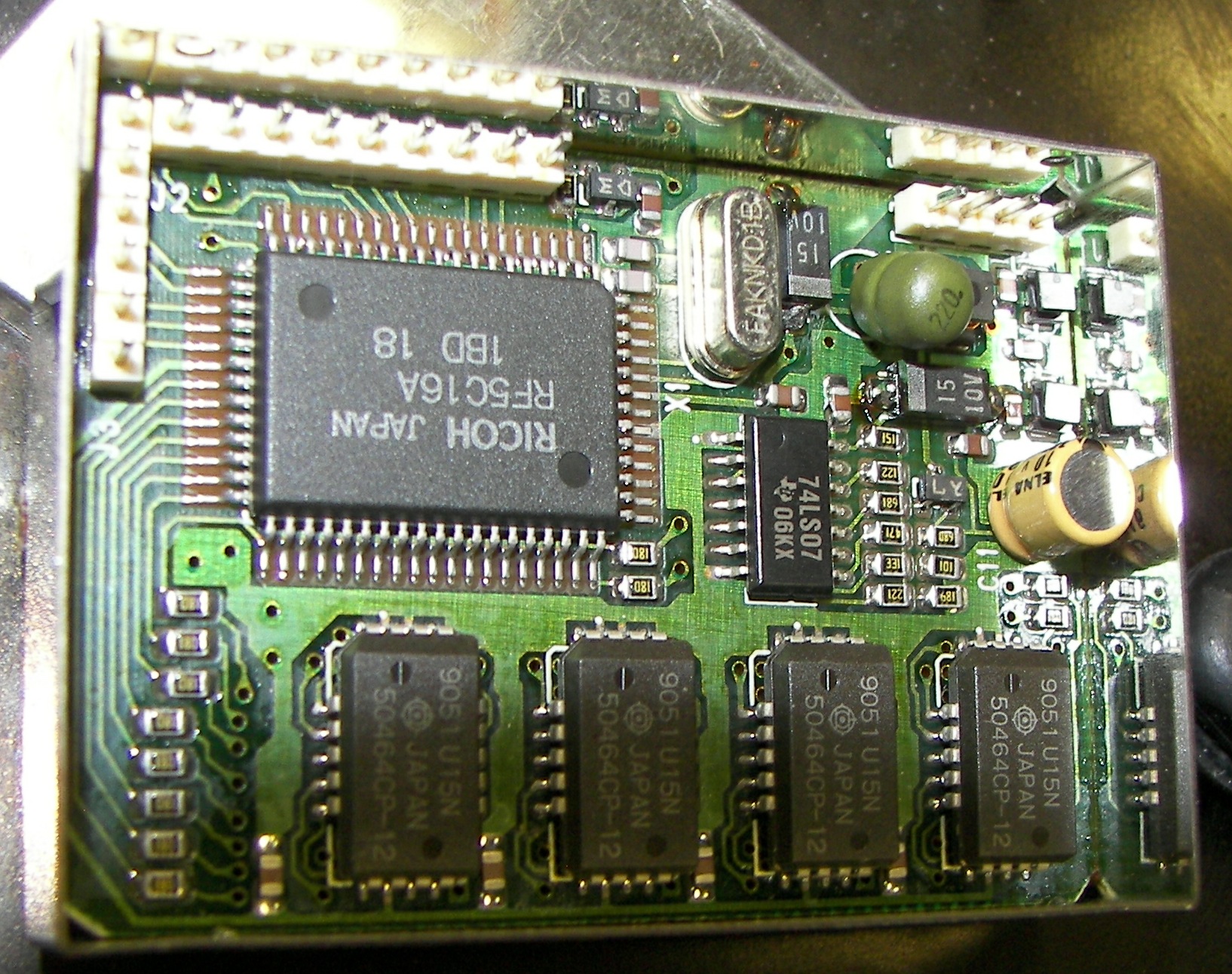
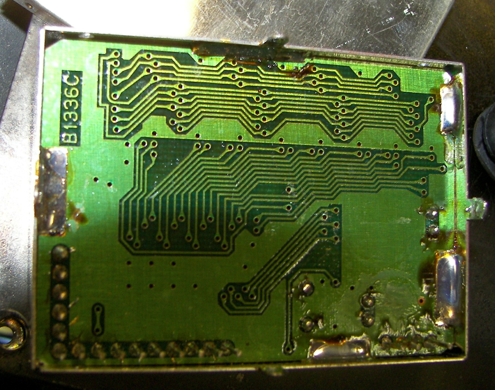
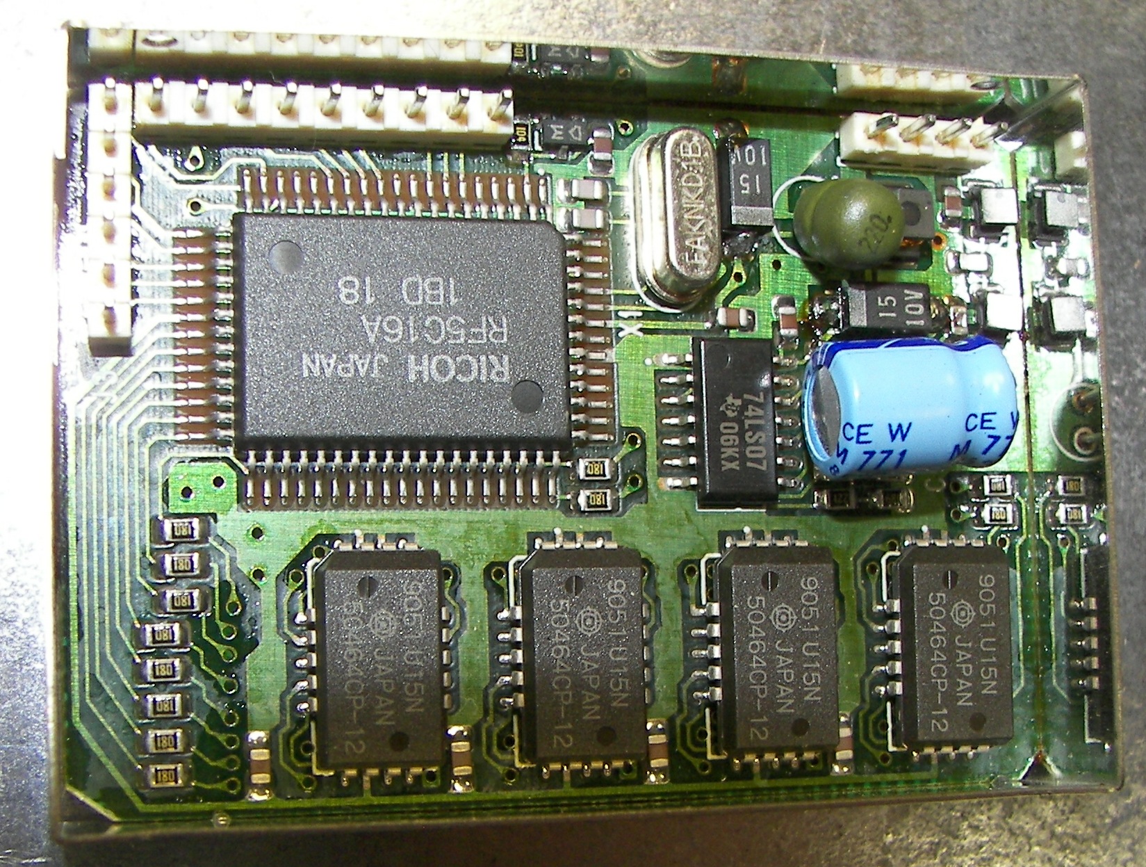



There were two problems on this otherwise fine communications receivers. These receivers run very hot inside. Icom should have added a fan. You should add a fan! Finding 1991 date codes in the unit, I was not too surprised that some attention would be needed.
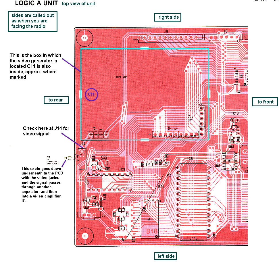
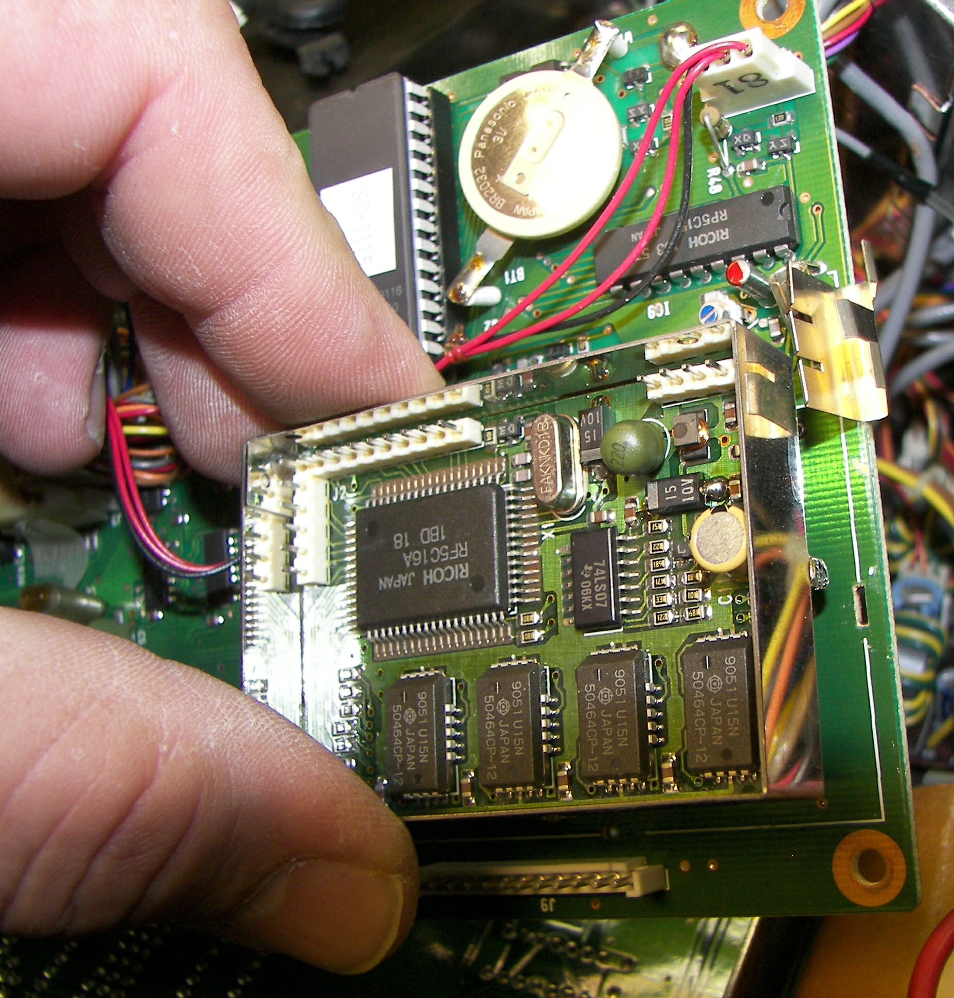
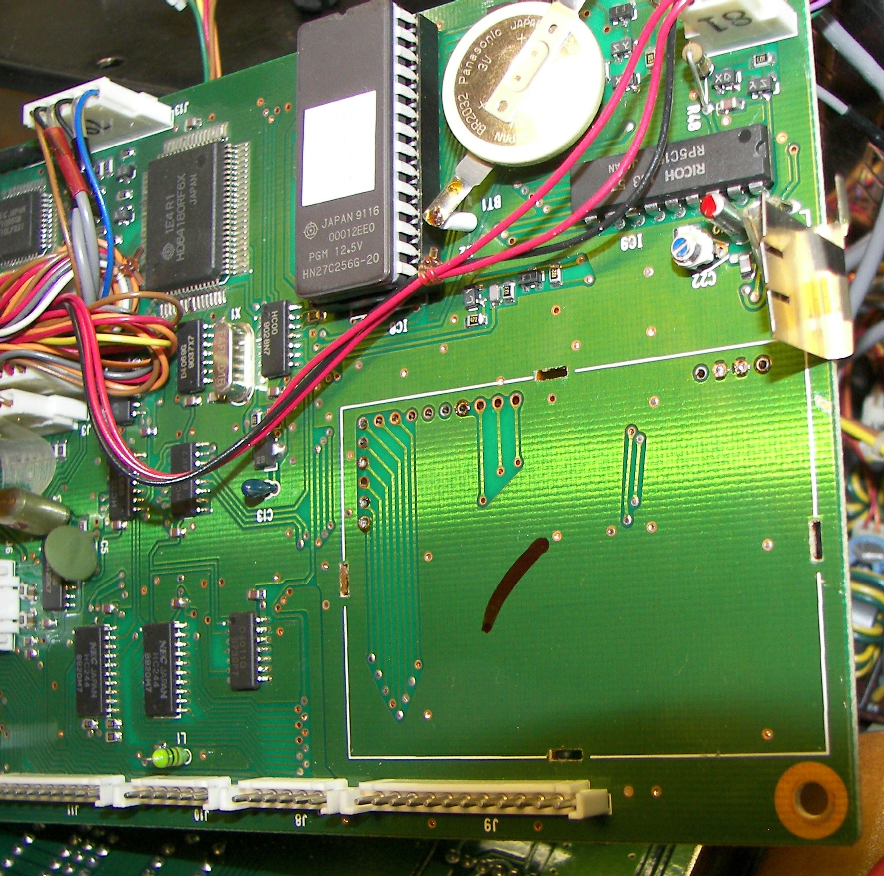
The first problem is a distorted video signal. This was caused primarily by a bad capacitor C11 on the video generator board, called the CRTC board. The board can be removed and repaired by a competent electronics technician. The job requires desoldering pins that go through plated-through holes in regular lands and also through those pesky ground planes on a dual-sided board. If this sounds intimidating, take it as a warning to be very careful with this work or you can ruin the job.
The way it fails is that C11 is in a closed-in box mounted on a board which is in another closed-in box, and this is mounted under a bracket with yet another box on it. Therefore the blasted thing gets very warm and the poor capacitor dries up and loses capacitance - and at that point it cannot pass the low frequency (V sync) part of the video synchronizing signal and the CRT picture goes to pot.
The easy way to make nearly certain that C11 is giving you the problem is to get access to the Logic A unit and test with a scope at J14 for video. J14 is where the signal from the CRTC board leaves the enclosures via the LOGIC A board. J14 is cramped and it is hard to get the probe there, so use a mini-clip. There is only one gray cable going into the rear side of the Logic A and B box. It's the video signal cable.
There are two ways to isolate the problem. They amount to the same thing.
1. Disconnect the video signal cable from J14. (you would have to already have done quite a bit of disasembly).
- or -
2. Trace this video signal cable by hand. It will go into a bundle of like cables through a hole in the chassis and then out towards the rear panel jacks board (called the "CONNECT A B UNIT"). Find where it plugs into its jack on the unit. Unplug the cable from the CONNECT A B UNIT.
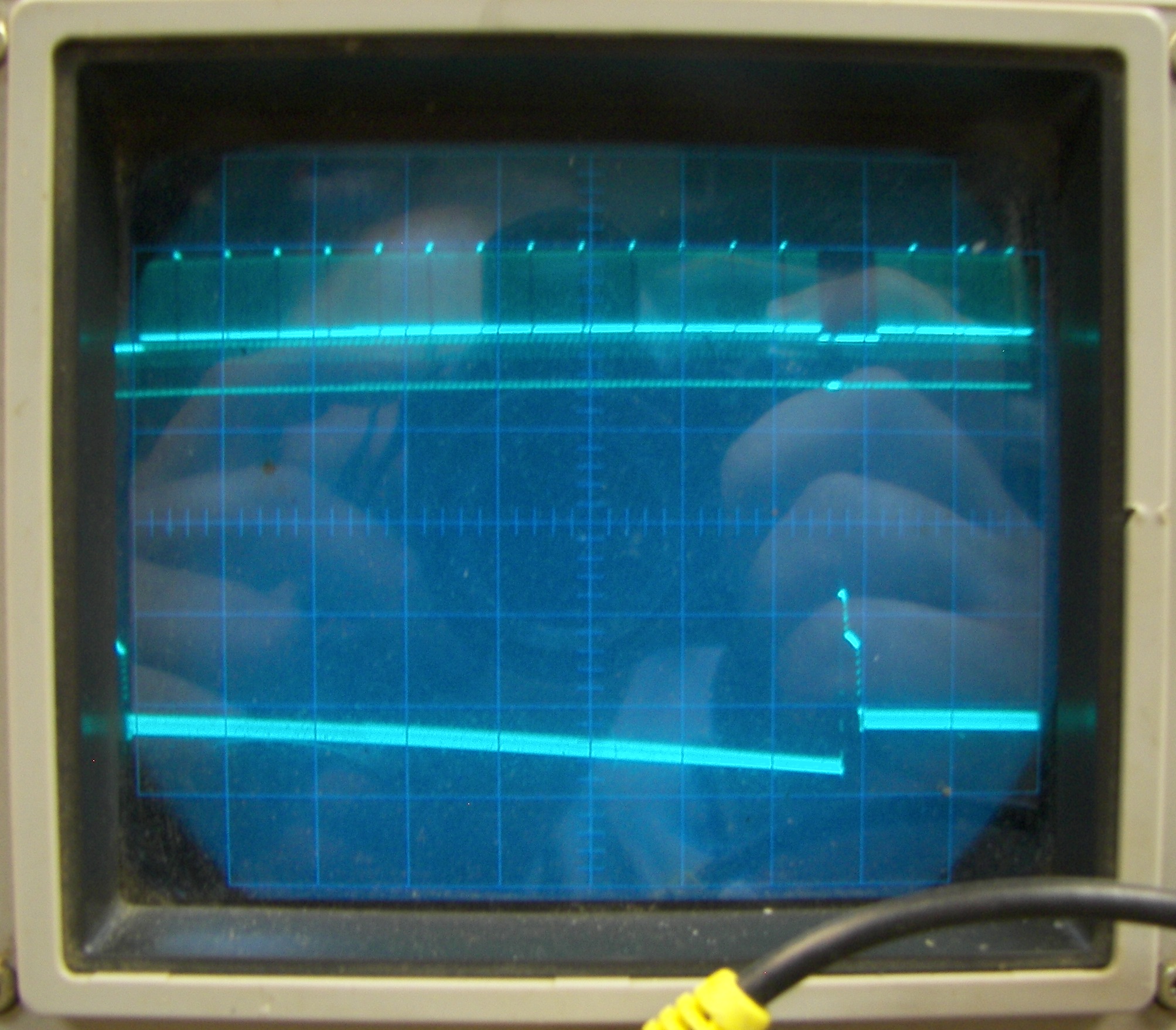
To evaluate this test, watch the scope and then disconnect the cable and see if the video straighens up. You need to know what a typical video signal looks like (the upper trace here is an example) -do not worry about the level, merely the appearance. It should have a clearly defined top (signal) and bottom (synchronizing) section as shown. If the video waveform being monitored at LOGIC A J14 becomes good or substantially improved, then C11 is the likely cause. Why does it matter if you disconnect the cable? Simple. The other end of the cable feeds the video signal to a video switch/amplifier IC. Inside the IC is a resistive load. So, taking the load away diminishes the effect of the bad capacitor on the signal. Of course the scope is also a load, but it is so light a load that it does not reasonably affect the signal.
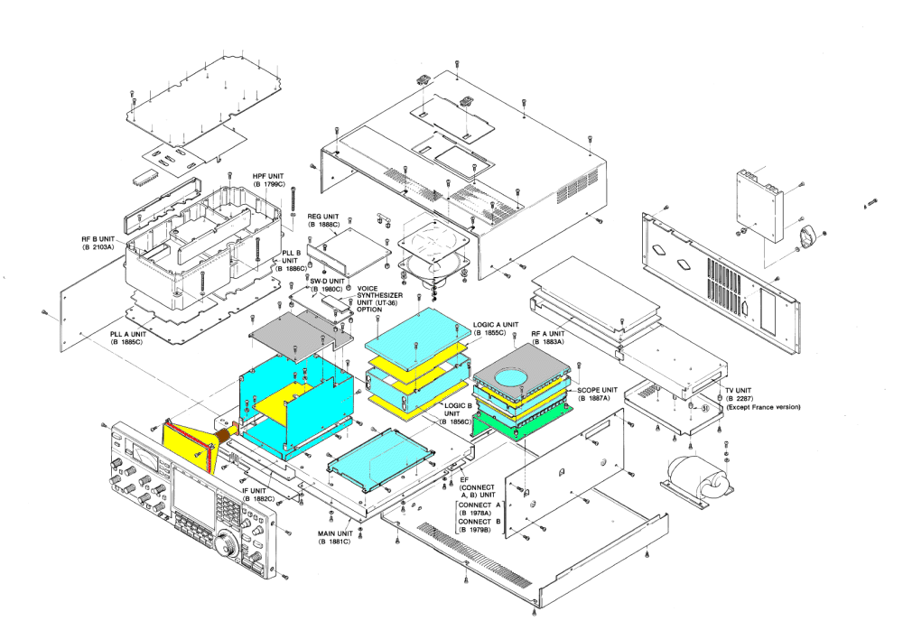
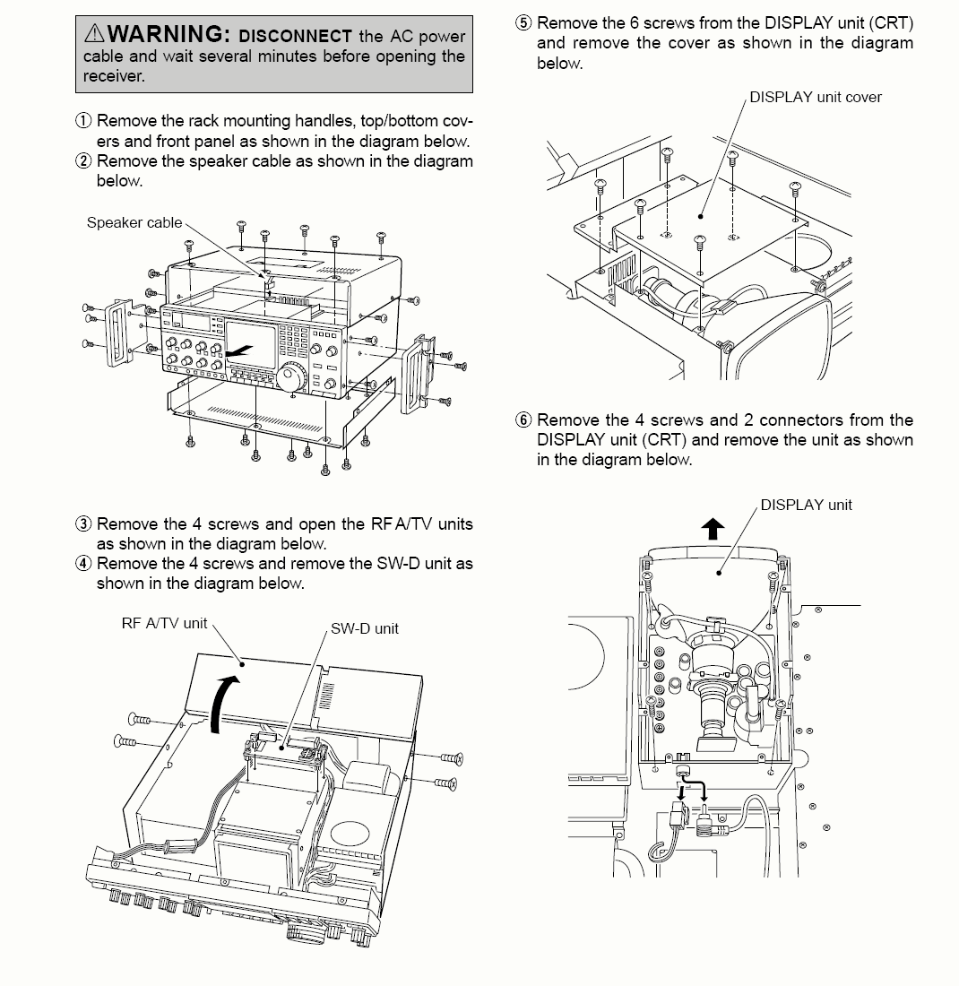
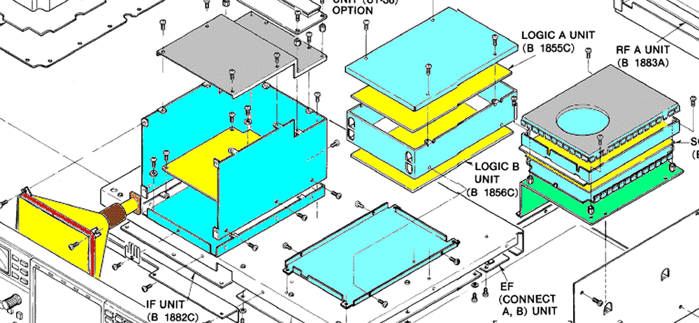
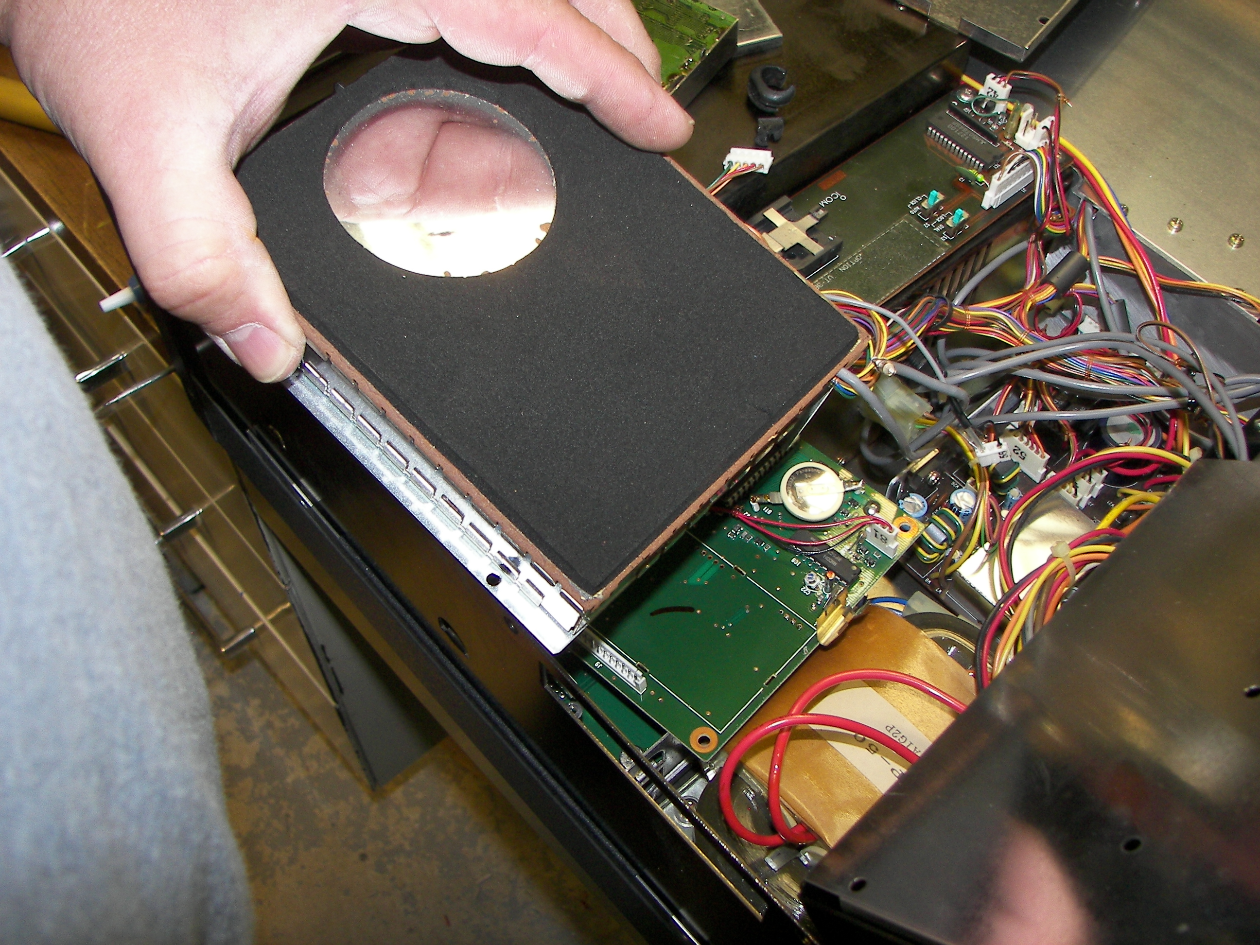
Now, how to get at the underside of the CRTC board to desolder C11? Just take the radio apart to get to the Logic A B unit as shown in the pictures. Good luck. Don't break it.
This done, and reassembled, the display is now perfectly readable. I hope reading this was as much fun for you as doing the repair and posting it was for me. Unfortunately, the monitor has some component failures too. No problem for me, I used to own a TV shop and I've seen this before. After I did the above repair, I searched to see if there was any kind of cooling kit. I found a website where Traian Belinas, YO9FZS, has told how to add a fan and also written interestingly about the CRT and video troubles including C11. Be sure to find his web page on this subject.
Next: The second problem, bad vertical linearity on the CRT display. It will get a thorough checkout, repair, and alignment.